IPE300 series engineering VFD Optional peripheral accessories
-355-
3. The values on the left and right sides of "/" indicate the recommended cables for heavy and light
loads respectively.
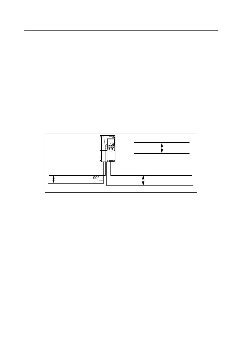
D.4.4 Cable arrangement
Motor cables must be arranged away from other cables. The motor cables of several inverters can be
arranged in parallel. It is recommended that you arrange the motor cables, input power cables, and
control cables separately in different trays. The output dU/dt of the inverters may increase
electromagnetic interference on other cables. Do not arrange other cables and the motor cables in
parallel.
If a control cable and power cable must cross each other, ensure that the angle between them is 90
degrees.
The cable trays must be connected properly and well grounded. Aluminum trays can implement local
equipotential.
The following figure shows the cable arrangement.
Input power cable
Control cable
Control cable
Motor cable
Motor cable
Power cable
Min. distance:
200mm
Min. distance:
500mm
Min. distance:
300mm
Figure D-3 Cable routing distance
D.4.5 Insulation inspection
Check the motor and the insulation conditions of the motor cable before running the motor.
1. Ensure that the motor cable is connected to the motor, and then remove the motor cable from the
U, V, and W output terminals of the VFD.
2. Use a megohmmeter of 500V DC to measure the insulation resistance between each phase
conductor and the protection grounding conductor. For details about the insulation resistance of
the motor, see the description provided by the manufacturer.
Note: The insulation resistance is reduced if it is damp inside the motor. If it may be damp, you need
to dry the motor and then measure the insulation resistance again.
D.5 Breaker and electromagnetic contactor
You need to add a fuse to prevent overload. You need to add a fuse to prevent overload.
You need to configure a manually manipulated molded case circuit breaker (MCCB) between the AC
power supply and VFD. The breaker must be locked in the open state to facilitate installation and
inspection.

 Loading...


