IPE300 series engineering VFD Extension card
-313-
it blinks periodically after the extension card is
properly connected to the control board (the period
is 1s, on for 0.5s, and off for the other 0.5s);
and it is off when the extension card is
disconnected from the control board.
Network connection
status indicator
This indicator is on when the physical connection to
the upper computer is normal;
it is off when the upper computer is disconnected.
Network communication
status indicator
This indicator is on when there is data exchange
with the upper computer;
it blinks when there is no data exchange with the
upper computer.
This indicator is on after the control board feeds
power to the communication card.
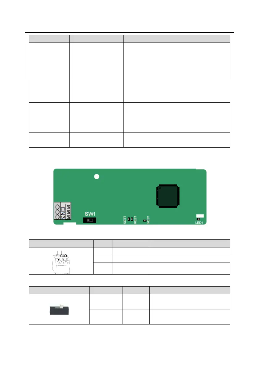
A.7.3 CANopen communication card(EC-TX505) and CAN master/slave control communication
card(EC-TX511)
The EC-TX505/511 communication card is user-friendly, adopting spring terminals.
CANopen bus high level signal
CANopen bus low level signal
Terminal resistor switch function description:
CAN_H and CAN_L are not connected
to a terminal resistor.
CAN_H and CAN_L are connected to
a terminal resistor of 120 Ω.

 Loading...


