IPE300 series engineering VFD Extension card
-328-
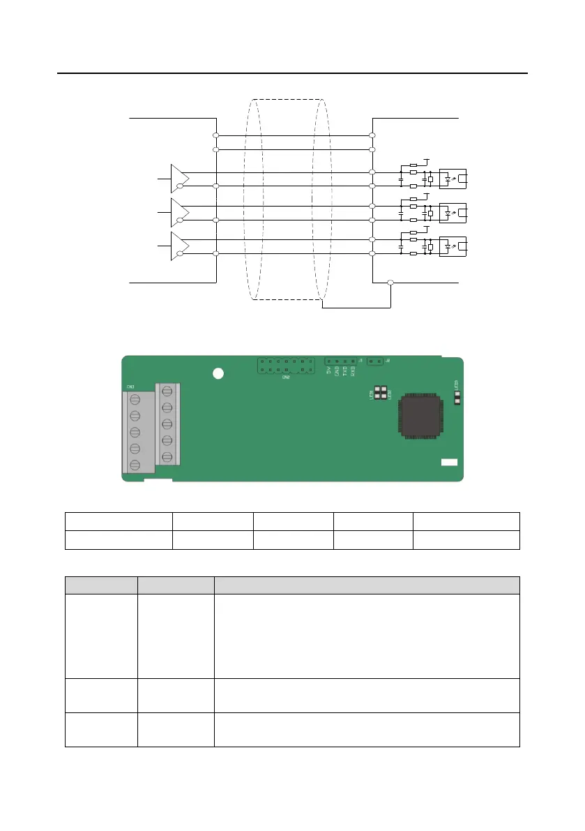
Z-
Z
+
B-
B
+
A-
A
+
PE
A-
B-
Z-
A+
B+
Z+
Differential
output
VCC
0V
Use shielded cable
PWR
PGND
PWR
PWR
PWR
PG card
Differential
encoder
A.8.5 24V Multi-function incremental PG card (EC-PG507-24)
The terminals are arranged as follows:
Indicator definition:
This indicator is on when the card is establishing a connection
with the control board; it blinks periodically after the card is
properly connected to the control board (the period is 1s, on for
0.5s, and off for the other 0.5s); and it is off when the card is
disconnected from the control board.
This indicator is off when A1 and B1 of the encoder are
disconnected; it is on when the encoder pulses are normal.
This indicator is on after the control board feeds power to the
card.

 Loading...


