IPE300 series engineering VFD Installation guidance
-23-
R
S
T
W
V
U
PE
M
22kW and higher
P1
(+)
DC reactor
3-phase power
660V±15%
50/60Hz
(-)
Input
reactor
Input filter
Fuse
DC-
Braking
resistor
DC+
Braking unit
Output
reactor
Output
filter
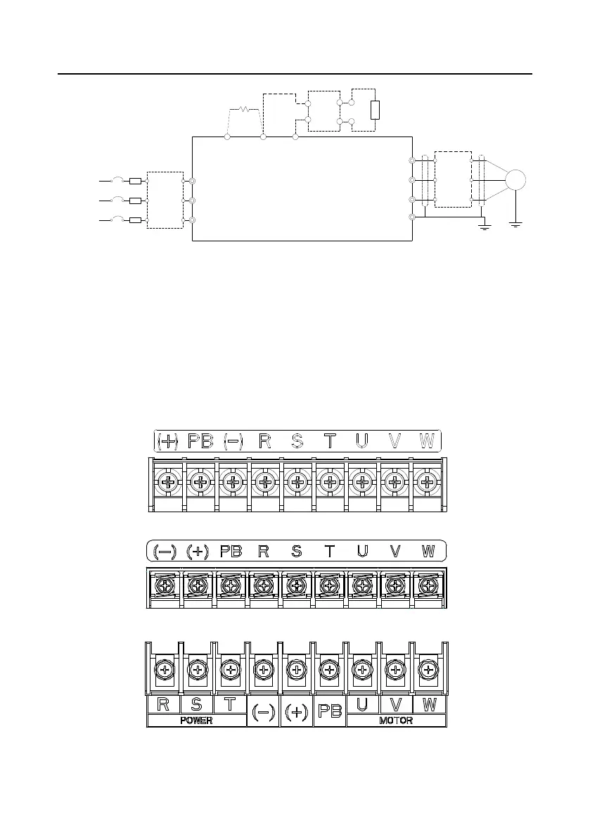
Figure 4-8 Main circuit wiring diagram for AC 3PH 520V(-15%)–690V(+10%)
Note:
The fuse, DC reactor, braking resistor, input reactor, input filter, output reactor and output filter are
optional parts. For details, see “Appendix D Optional peripheral accessories".
P1 and (+) have been short connected by default. If you need to connect to external DC reactor,
remove the short-contact tag of P1 and (+).
Before connecting the braking resistor, remove the yellow warning label with (+) and (-) from the
terminal block; otherwise, poor contact may occur.
4.3.2 Terminal diagram of the main circuit
Figure 4-9 3PH 380V 0022 and lower
Figure 4-10 3PH 380V 0030–0037
Figure 4-11 3PH 380V 0045–0110

 Loading...


