IPE300 series engineering VFD Extension card
-332-
Differential
encoder
Z-
Z+
B-
B+
A-
A+
PE
A-
B-
Z-
A+
B+
Z+
Differential
output
VCC
0V
Use the shielded cable
PWR
PWR
PWR
PG card
PWR
PGND
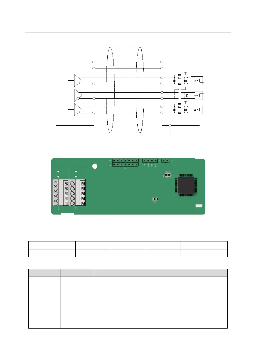
A.8.6 Simplified incremental PG card (EC-PG507-12)
The terminals are arranged as follows:
The dual in-line package (DIP) switch SW1 is used to set the voltage class (5V or 12V) of the power
supply of the encoder. The DIP switch can be operated with an auxiliary tool.
Indicator definition:
This indicator is on when the extension card is establishing a
connection with the control board;
it blinks periodically after the extension card is properly connected
to the control board (the period is 1s, on for 0.5s, and off for the
other 0.5s);
and it is off when the extension card is disconnected from the
control board.

 Loading...


