IPE300 series engineering VFD Installation guidance
-18-
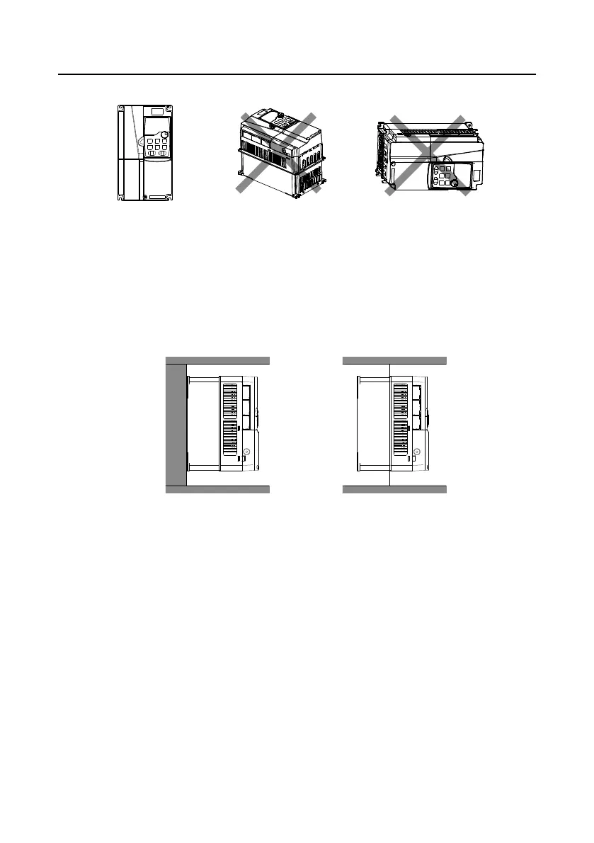
NG
B. Horizontal installation C. Transverse installation
OK
NG
A. Vertical installation
Figure 4-1 VFD installation direction
4.2.3 Installation method
There are three kinds of installation modes based on different VFD dimensions.
Wall-mounting: suitable for 380V 0315 and lower, and 660V 355kW and lower.
Flange-mounting: suitable for 380V 0200 and lower, and 660V 220kW and lower.
Floor-mounting: suitable for 380V 0220–0500, and 660V 250–630kW.
Wall-mounting
Flange-mounting
Figure 4-2 Installation mode
1. Mark the installation hole positions. For details about the installation hole positions, see
Appendix D Dimension.
2. Mount the screws or bolts onto the designated positions.
3. Lean the VFD against the wall.
4. Tighten the screws.
Note:
Flange-mounting plate is a must for the 380V 01R5 –0075 VFD models that adopt
flange-mounting mode; while the 380V 0090–0200 and 660V 22–220kW models need no
flange-mounting plate.
Optional installation base is available for the 380V 0220–0315 and 660V 250–355kW VFD
models. The base can hold an input AC reactor (or DC reactor) and an output AC reactor.

 Loading...


