IPE300 series engineering VFD Extension card
-304-
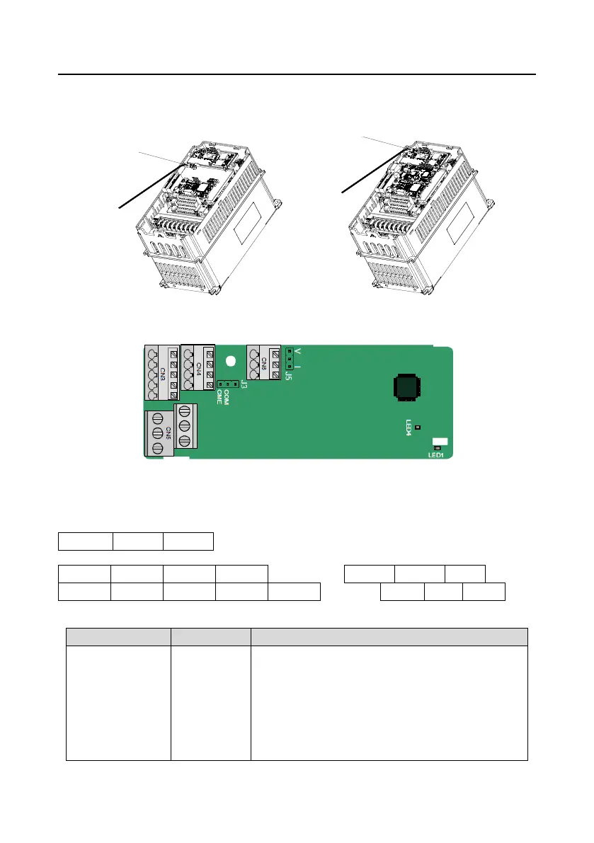
A.3 Wiring
Ground a shielded cable as follows:
Grounding position of the
shielded cable
Grounding position of
the shielded cable
Figure A-4 Extension card grounding diagram
A.4 I/O extension card 1 (EC-IO501-00)
The terminals are arranged as follows:
CME and COM are shorted through J3 before delivery, and J5 is the jumper for selecting the output
type (voltage or current) of AO2.
Indicator definition:
This indicator is on when the extension card is
establishing a connection with the control board;
it blinks periodically after the extension card is properly
connected to the control board (the period is 1s, on for
0.5s, and off for the other 0.5s);
and it is off when the extension card is disconnected from
the control board.

 Loading...


