IPE300 series engineering VFD Extension card
-306-
1. Contact capacity: 3A/AC250V,
1A/DC30V
2. Cannot be used as high frequency
digital output
Common contact of
relay 3
Common contact of
relay 4
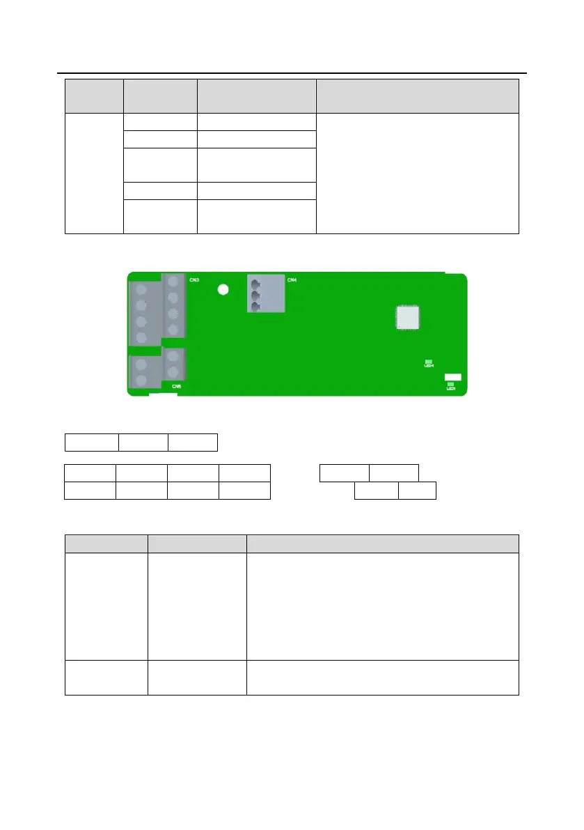
A.5 I/O extension card 2 (EC-IO502-00)
The terminals are arranged as follows:
Indicator definition:
This indicator is on when the extension card is
establishing a connection with the control board;
it blinks periodically after the extension card is properly
connected to the control board (the period is 1s, on for
0.5s, and off for the other 0.5s);
and it is off when the extension card is disconnected
from the control board.
This indicator is on after the IO extension card is
powered on by the control board.
EC-IO502-00 extension card can be used in scenarios where the I/O interfaces of an IPE300 VFD
cannot meet the application requirements. It can provide four digital inputs, one PT100 temperature

 Loading...


