IPE300 series engineering VFD Extension card
-322-
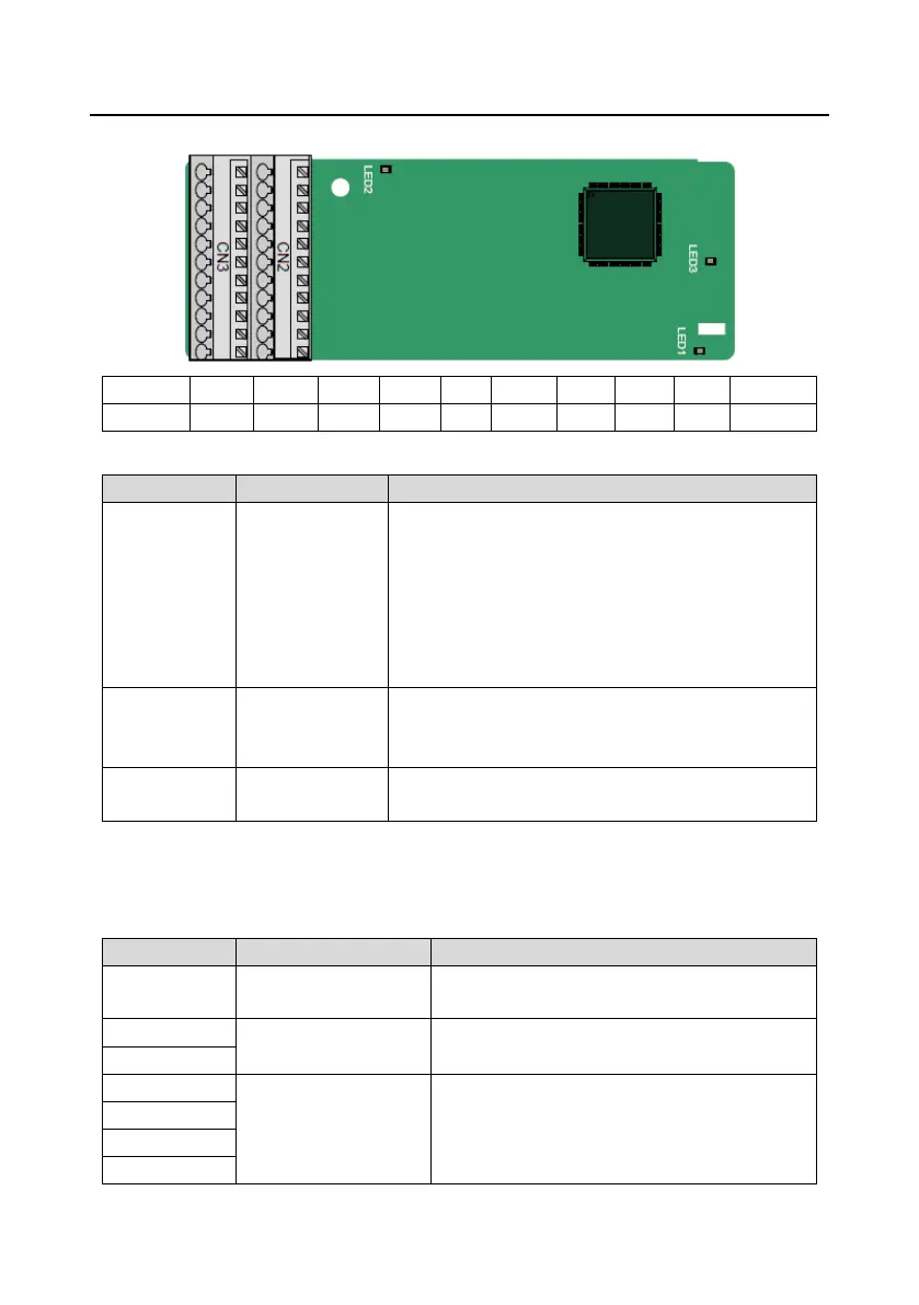
A.8.3 Resolver PG card (EC-PG504-00)
Indicator definition:
This indicator is on when the extension card is
establishing a connection with the control board;
it blinks periodically after the extension card is properly
connected to the control board (the period is 1s, on for
0.5s, and off for the other 0.5s);
and it is off when the extension card is disconnected from
the control board.
This indicator is off when the encoder is disconnected; it is
on when the encoder signals are normal; and it blinks
when the encoder signals are not stable.
This indicator is on after the control board feeds power to
the PG card.
EC-PG504-00 can be used in combination with a resolver of excitation voltage 7 Vrms. It is
user-friendly, adopting spring cage terminals.
EC-PG504-00 terminal functions:
It is connected to the ground for enhancing the
anti-interference performance.
Recommended resolver transformation ratio: 0.5

 Loading...


