IPE300 series engineering VFD Product overview
-15-
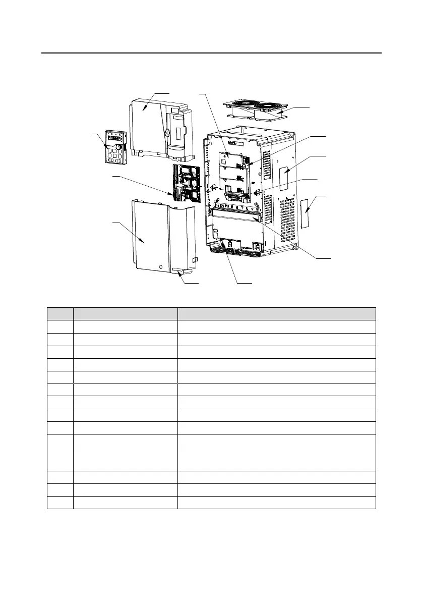
3.7 Structure
The VFD structure is shown in the following figure (taking the 380V 0030 VFD model as an example).
Figure 3-8 Structural diagram
Protects internal components and parts.
For details, see section “Keypad instruction”.
Protects internal components and parts.
Optional. For details, see “Extension card”.
Protects the control board and install extension card.
For details, see section “Extension card”.
For details, see section “Product overview”.
Control circuit terminals
For details, see section “Installation guidance”.
Cover plate of heat emission
hole
Optional. Cover plate can upgrade protection level,
however, as it will also increase internal temperature,
derated use is required.
For details, see section “Installation guidance”.
IPE300 product series label
For details, see section “Model designation code”

 Loading...


