IPE300 series engineering VFD Installation guidance
-31-
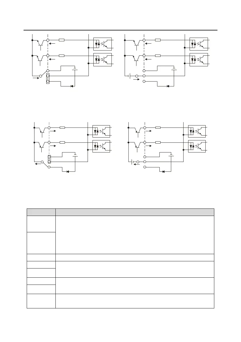
S1
S2
COM
PW
+
24V
COM
+ 24V
Internal power(NPN mode)
S1
S2
COM
PW
+ 24V
COM
+
24V
External power(NPN mode)
+ 24V
Figure 4-20 NPN mode
If input signal comes from PNP transistor, set the U-type short-contact tag based on the power used
according to the following figure.
S1
S2
COM
PW
+ 24V
COM
+ 24V
External power(PNP mode)
S1
S2
COM
PW
+ 24V
COM
+ 24V
Internal power(PNP mode)
Figure 4-21 PNP mode
4.4.3 Control circuit wiring of the I/O card 2
Independent PT100 and PT1000 inputs: PT1+ to PT100 resistor, PT2+ to PT1000
resistor
1. Resolution rate: 1°C
2. Range -20°C –150°C
3. Detection precision: 3°C
4. Support drop protection
Reference zero potential of PT100/PT1000
RO3 output; RO3A: NO; RO3C: NC;
Contact capacity: 3A/AC250V, 1A/DC30V
RO4 output; RO4A: NO; RO4C: common;
Contact capacity: 3A/AC250V, 1A/DC30V
Used to provide input digital working power from the external to the internal
Voltage range: 24(-20%)–48VDC(+10%), 24(-10%)–48VAC(+10%) voltage input

 Loading...


