IPE300 series engineering VFD Dimension drawings
-338-
Appendix C Dimension drawings
C.1 What this chapter contains
This chapter describes the dimension drawings of VFDs. which uses millimeter (mm) as the unit.
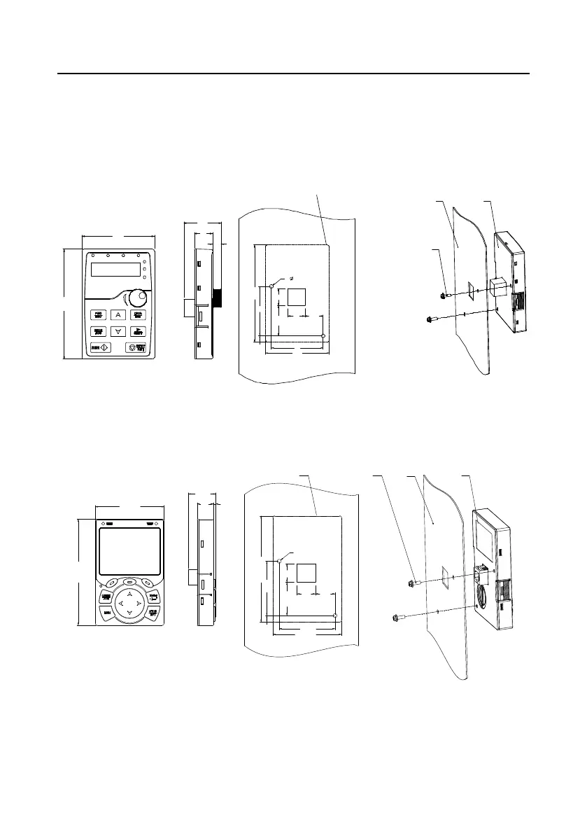
C.2 Keypad structure
C.2.1 LED keypad structure
Keypad
2
-
M
3
x
10
combination screw
Panle
19
2
-
4
6.7
71.3
34.4
19 20.4
56
58
109.3
Installation hold dimensions and diagram for key installation without bracket
18
71.3
8.6
109.3
37.1
Outer outline of the keypad
Figure C-1 LED keypad structure
C.2.2 Optional LCD keypad structure
Installation hole dimensions and diagram for key installation without bracket
Ou
ter outline
of the keypad
2
-
M
3
×
8
tapping
screw
Panel
Keypad
109.3
71.3
28.5
16.8
2.5
109.3
56
6.7
71.3
58
2- ø4
1934.4
19
20.4
Figure C-2 Optional LCD keypad structure
C.2.3 Keypad mounting bracket
Note: The external keypad can be mounted directly with M3 threaded screws or with a keypad

 Loading...


