IPE300 series engineering VFD Extension card
-311-
A.7 Communication cards
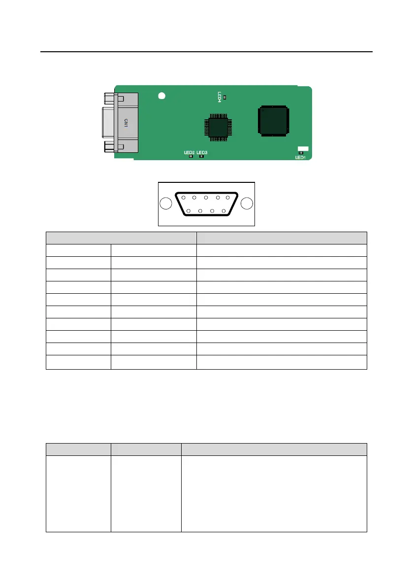
A.7.1 PROFIBUS-DP communication card (EC-TX503)
CN1 is a 9-pin D-type connector, as shown in the following figure.
Isolated power supply of 5 V DC
PROFIBUS cable shielding line
+5V and GND_BUS are bus terminators. Some devices, such as the optical transceiver (RS485),
may need to obtain power through these pins.
Some devices use RTS to determine the sending and receiving directions. In normal applications,
only A-Line, B-Line, and the shield layer need to be used.
Indicator definition:
This indicator is on when the extension card is
establishing a connection with the control board;
it blinks periodically after the extension card is properly
connected to the control board (the period is 1s, on for
0.5s, and off for the other 0.5s);
and it is off when the extension card is disconnected
from the control board.

 Loading...


