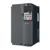
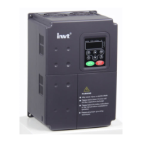
IPE300 series engineering VFD Extension card
-333-
This indicator is off when A1 and B1 of the encoder are
disconnected; it is on when the encoder pulses are normal.
This indicator is on after the control board feeds power to the PG
card.
EC-PG507-12 can work in combination with multiple types of incremental encoders through various
external wiring modes, which are similar to the wiring modes of EC-PG505-12. EC-PG507-12
terminal function description:
It is connected to the ground for enhancing the
anti-interference performance.
Voltage: 5V/12V ± 5%
Max. output: 150 mA
Select the voltage class through SW1 based on the
voltage class of the used encoder. (PGND is isolation
power ground)
1. Applicable to 5V/12V push-pull encoders
2. Applicable to 5V/12V OC encoders
3. Applicable to 5V differential encoders
4. Response frequency: 400kHz
5. Supporting the encoder cable length of up to 50m

 Loading...


