83
Chapter 4: Repair Procedures
Logic Board Procedures
Logic board replacement
Tools Required:
n Phillips head screwdriver
n
5
/
32
-in Allen wrench
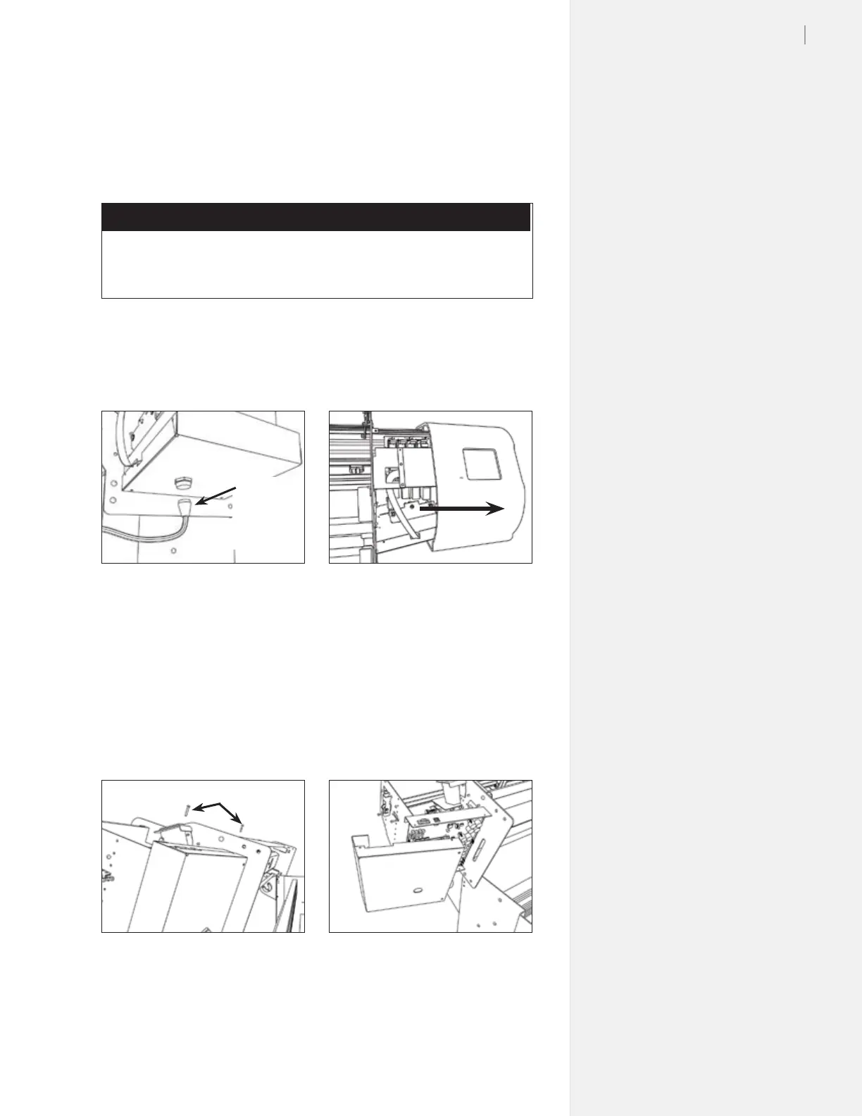
1. Unplug the take-up motor cable from the bottom of the ma-
chine. Unplug the power and serial cable. (Figure 79.)
2. Remove the right side cover of the machine. (Figure 80.)
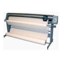
3. Remove the four Phillips screws that hold the
logic board cover
on. (Figure 81.)
4. Make sure you are grounded with a static grounding strap. For
now, leave the new logic board in its packaging. Remove the
logic board cover on the FlexJet. Carefully unplug the take-up
connector from the logic board before completelly removing
the cover. (Figure 82.)
Figure 79. Unplug the take-up motor.
Take-up
motor
cable
Figure 80. Remove the right cover.
Figure 81. Unscrew the PCB cover.
Figure 82. Remove the logic board cover.
Cover screws (rear)
5. Label the cables to make it easy to rematch during re-assembly.
Carefully unplug the connections from the board. Remove the
six silver phillips screws holding the board in the machine.