85
Chapter 4: Repair Procedures
8. Install the new logic board into the machine. Carefully insert
the serial port end into the holes in the metal bracket rst.
Tighten the six phillips screws that hold the board in making
sure not to overtighten them.
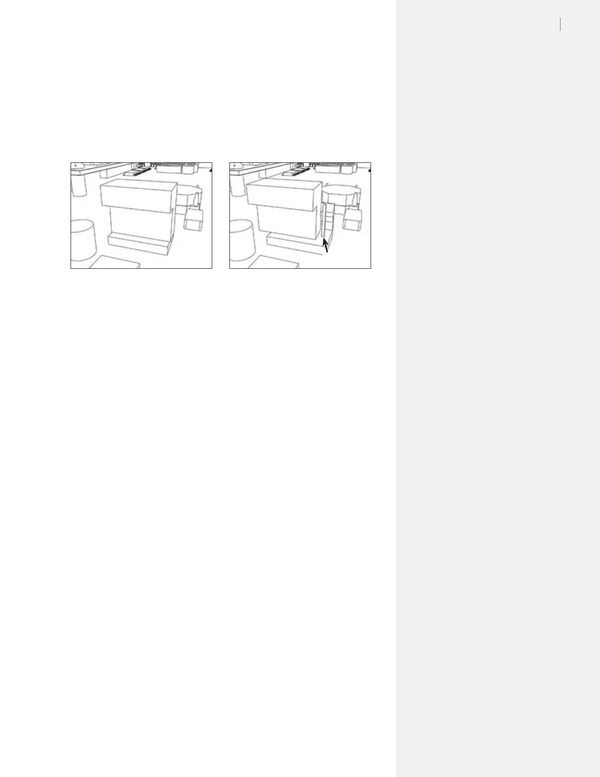
9. Plug in all the wire connections to the board. Make sure the
connectors are not off by a pin. (Figure 85.)
10. Install the board cover, making sure to plug in the take-up wire
connections to the board rst. Make sure there are no wires or
cables pinched between the cover and the body.
11. Install the right side plastic cover.
12. Connect the power and communication cables.
13. Test the machine for proper functioning. Press the arrows on
the keypad to make sure all directions are working.
14. If problems arise call Ioline Customer Service.
Figure 85. It’s easy to miss a pin when plugging in the logic board. Inspect the con-
nections to make certain the board is properly connected.
Right Wrong