iPECS UCM
Installation Manual Issue 1.1
32
3.3.1.3 UCM Synchronization
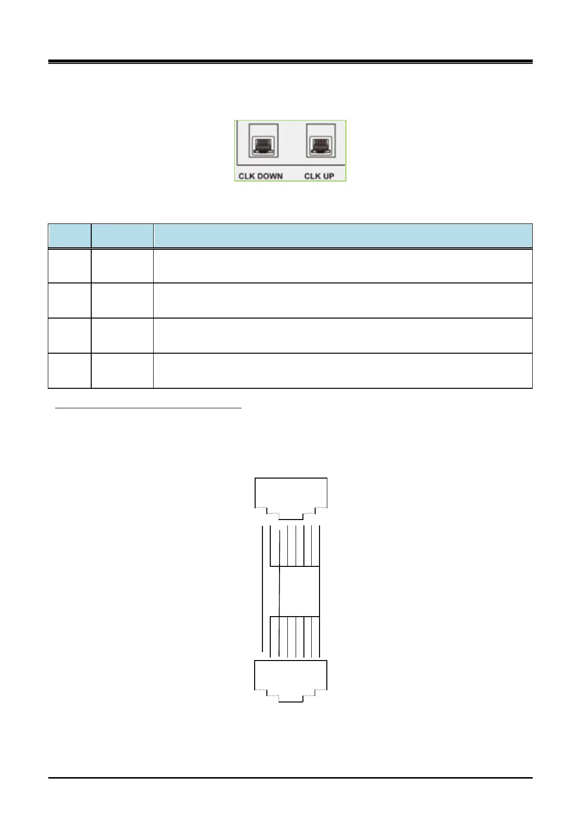
UCM Synchronization is connected to CLK_UP port and CLK_DOWN port on RJ45 in the rear side.
Figure 3-6 UCM-MGC3 CLK DOWN & CLK UP LED
Table 3-1 Description of the Synchronization LED Status
Port LED Color Description
CLK_
UP
Yellow
LED ON: Receiving 8KHz system clock from UCM-MDTM2 directly
LED OFF: Not Receiving
CLK_
DOWN
Yellow
LED ON: Receiving 8KHz system clock from UCM-MDTM2 directly
LED OFF: Not Receiving
CLK_
UP
Blue
LED ON: Receiving 8KHz system clock from CLK_DOWN port of other UCM-MGC3
LED OFF: Not Receiving
CLK_
DOWN
Blue
LED ON: Receiving 8KHz system clock from CLK_UP port of other UCM-MGC3
LED OFF: Not Receiving
Ethernet straight cable (UTP -5) can be used as UCM-SYNC cable. CLK_UP port should be connected to
CLK_DOWN port of other UCM-MGC3 and CLK_DOW N port to CLK_UP port of other UCM-MGC3.
UCM Synchronization Cable Connection
CLK_DOWN Port
1
2
3
4
5
6
7
8
CLK_UP Port
CLK_IN CLK_OUT
CLK_OUT CLK_IN
GND
1
2
3
4
5
6
7
8
Figure 3-7 UCM-SYNC cable pin assignment