iPECS UCM
Installation Manual Issue 1.1
72
3.5.7 UCM-VPCM Installation
The VPCM can be installed in either UCM-MGC3 or UCM-1URMC. When installed in the UCM-MGC3, it can
be in any slot. Hot Swap is supported to enable inserting/removing the Gateway Module while power is
supplied to the cabinet.
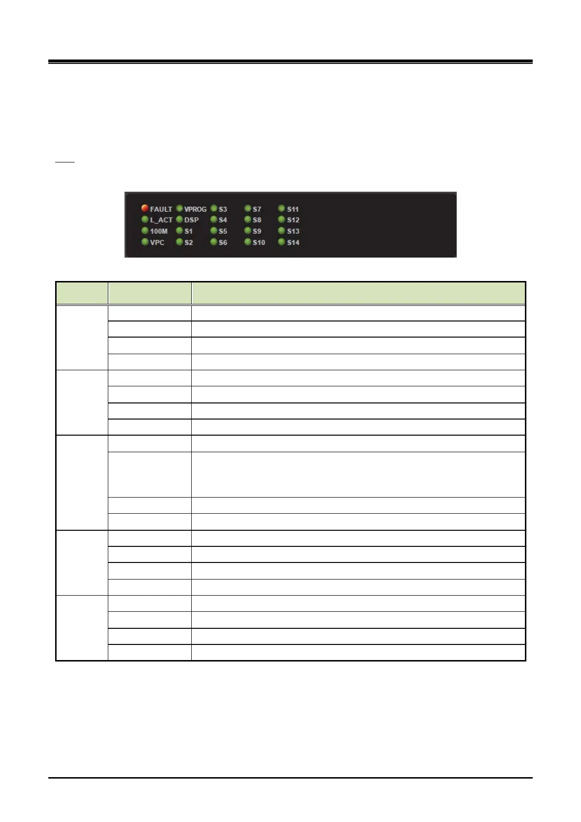
There are 20 LED on the VPCM front panel for the status and diagnosis as shown in the Table 3-14.
LED
Table 3-14 VPCM Status LED
Column Silk (VPCM) VPCM
1
FAULT Fault (OFF - Normal, ON - Fault)
L_ACT Ethernet Link/ ACT (External) : ON - Idle, Blink – Traffic
100M Ethernet Speed (External) : OFF - 10Mbps, ON - 100Mbps
VPC VPC LED (OFF - Normal, ON - Fault)
2
VPC(FPGA) Initialization (ON - Success, OFF - Failure)
DSP DSP Initialization (ON - Success, OFF - Failure)
S1 Register (ON - Success, OFF - Failure)
S2 Polling - Toggle(30sec) when received polling command
3
S3 Board Status - Toggle(200ms) when the board is working
S4
DSP Active
- Toggle(600ms) when DSP is active
S5 Ramdisk full status - FULL(ON)
S6 eMMC memory full status - FULL(ON)
4
S7 IP Redirect Call - Connected(ON)
S8 Transcoding Call - Connected(ON)
Conference Call - Connected(ON)
S10 Voice Prompt Call - Connected(ON)
5
Total call count > 0 (ON)
S12 Total call count > 20 (ON)
S13 Total call count > 50 (ON)
S14 Total call count > 100 (ON)