iPECS UCM
Installation Manual Issue 1.1
41
3.3.1.5.3 UCM-PSUD Power Cable Connection
Determine the length of power cables taking into account of SYS – rectifier and rectifier – battery
voltage drop.
-48V cable connection
Pay attention to the cable color of -48V (blue) when assembling the cables.
Fix the cable to the terminal with a jig and do soldering.
Make sure to use an insulating shrink tube to prevent short circuit.
Use 8 AWG stranded wire.
Note)
Determine the length of power cables taking into account of SYS – rectifier and rectifier – battery
voltage drop.
GND cable connection
Fix the cable to the terminal with a jig and do soldering.
Use GND (Red/Black) cable.
Make sure to use an insulating shrink tube to prevent short circuit.
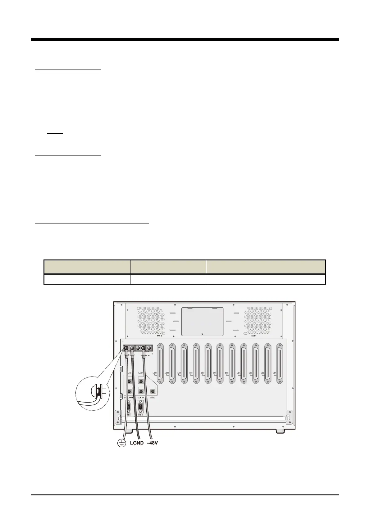
When PSUD is used for UCM-MGC3, connect the rectifier as shown in Figure 3-15 below. Make sure to
connect FGND and LGND to the rectifier instead of the system.
DC cable specification and connection
Table 3-3 DC cable specification
System Max Load Current Cable Specification
UCM-MGC3 30 A More thick than 8 AWG (8.4 SQ)
(Based on cable length 10m, allowable voltage drop 0.5V)
Figure 3-16 UCM-MGC3 Power Cable Connection after PSUD installation