iPECS UCM
Installation Manual Issue 1.1
68
3.5.6 UCM-MDTMX2 Installation
The UCM-MDTMX2 can be installed in any of the 11 slots of the UCM-MGC3 and can also be installed in the
UCM-1URMC. Hot Swap is supported to enable installing/removing while power is supplied to the cabinet.
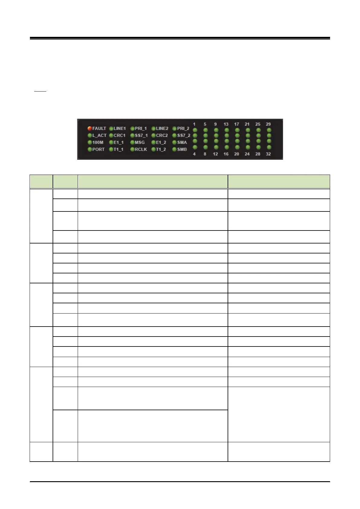
The UCM-MDTMX2 provides a Reset S/W, 20 LED for diagnostics and function display and 32 channel
statuses LED as shown in the Table 3-13.
LED
Table 3-13 UCM-MDTMX2 Status LED
Column
Silk MDTMX2 Remark
1
FAULT Fault (OFF - Normal, ON - Fault)
L_ACT Ethernet Link/ ACT (External)ON - Idle, Blink - Traffic
100M
Ethernet Speed (External)
OFF - 10Mbps, ON - 100Mbps
PORT MDTM Port (ON- Port #1, OFF- Port #2) Port Indication – by CPU GPIO 19
2
LINE 1 Line 1 Connection Status (ON : Good Status) Port #1
CRC 1 CRC #1 (ON - CRC is ON)
E1_1 Line Signaling Indication (ON : E1) Blink - L2 ~ L3 Abnormal
T1_1 Line Signaling Indication (ON : T1) Blink - L2 ~ L3 Abnormal
3
PRI_1 Line Signaling Indication (ON : PRI) Blink - L2 ~ L3 Abnormal
SS7_1 Line Signaling Indication (ON : SS7) Blink - L2 ~ L3 Abnormal
Master of Synchronization Group (ON : Master)
RCLK Reference Clock Indication (ON : Line1, OFF : Line2)
4
LINE 2 Line 2 Connection Status (ON : Good Status) Port #2
CRC 2 CRC #2 (ON - CRC is ON)
Line Signaling Indication (ON : E1)
T1_2 Line Signaling Indication (ON : T1) Blink - L2 ~ L3 Abnormal
5
PRI_2 Line Signaling Indication (ON : PRI) Blink - L2 ~ L3 Abnormal
SS7_2 Line Signaling Indication (ON : SS7) Blink - L2 ~ L3 Abnormal
SMA Synchronization Mode Indication A
SMA/SMB(0 : OFF, 1 : ON)
00 : Locking to Line clock
01 : Locking to Internal(Sys tem ) clock
10 : Internal(Free-run) mode
11 : Exclude DPLL (Using directly PLL
Block of Line I/F Framer)
SMB Synchronization Mode Indication B
6
1 29
4 32
Channel 1 ~ 32 Port #1 and #2 (Common use)