iPECS UCM
Installation Manual Issue 1.1
65
3.5.5 UCM-MDTM2 Installation
The UCM-MDTM2 can be installed in any of the 11 slots of the UCM-MGC3 and can also be installed in the
UCM-1URMC. Hot Swap is supported to enable installing/removing while power is supplied to the cabinet.
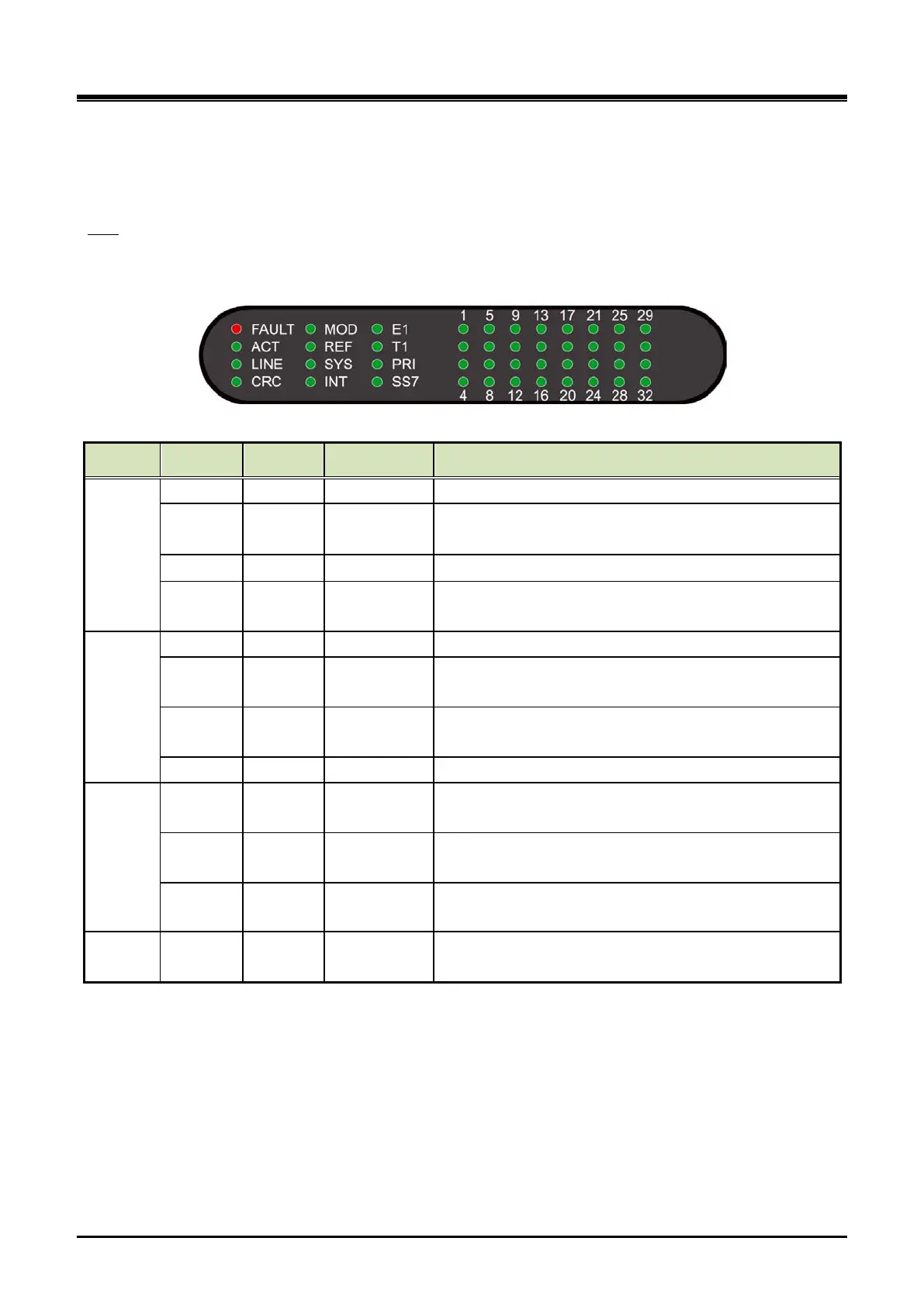
The UCM-MDTM2 provides a Reset S/W, 12 LED for diagnostics and function display and 32 channel
statuses LED as shown in the Table 3-12.
LED
Table 3-12 UCM-MDTM2 Status LED
Column LED Color Function Description
1
FAULT RED CPU status Off–Normal, On – Fault (or reset)
ACT GREEN ACT
PRI/SS7: Blink in L2 normal, ON in L3 normal
E1/T1: Blink in normal
LED ON at synchronization with remote digital trunk
CRC GREEN
CRC
ON/OFF
LED ON when CRC is on
2
MOD GREEN NT/ TE mode On : NT mode, Off : TE mode
REF GREEN
Reference
LED ON : Supply a Reference clock to other MDTM2
SYS GREEN
Reference
clock in
LED ON : Receive a Reference clock from other
MDTM2
INT GREEN Self Clock LED ON : Operating with Self Clock
3
E1/T1 GREEN LINE E1/T1
Gateway Module service mode. European mode (E1
ON)’ American mode ( T1 ON)
PRI GREEN
PROTOCOL
LED
LED ON when PRI is used
SS7 GREEN
PROTOCOL
LED
LED ON when Signaling System No.7 is used
4~11
CH1~32 GREEN Channel LED
LED corresponding to the channel is ON when a
channel is in service.