iPECS UCM
Installation Manual Issue 1.1
58
3.5.3 UCM-DSLM Installation
The UCM-DSLM can be installed on either UCM-MGC3 or UCM-1URMC. When installed on the UCM-MGC3,
it can be in any of the 11 slots. It can also be installed stand alone in UCM-1URMC.
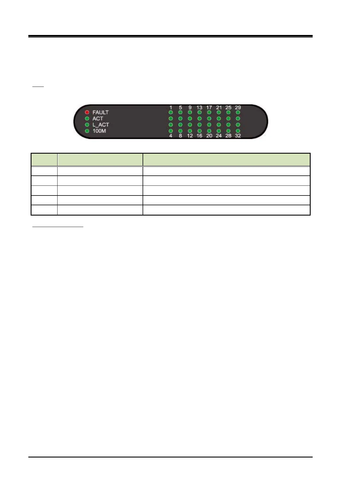
There are 36 LED on the UCM-DSLM front panel for the status and diagnosis as shown in the Table 3-10.
LED
Table 3-10 UCM-ASLM Status LED
LED LED Function Description
FAULT CPU status Off–Normal, On – Fault (or reset)
L_ACT Ethernet traffic (External port) Off – No traffic, Blink - Traffic
100M Ethernet speed (External port) Off - 10 Mbps, On - 100 Mbps
Off – not connected, On – Idle, Blink – busy
To install the UCM-DSLM on the UCM-1URMC, connect it to the iPECS UCM system through the RJ-45
connector marked “LAN” on the rear side of the cabinet.There is a 64 pin (LB) champ connector connected
through the PCB edge on the rear side of the cabinet:
Wiring Connectors
Wire each champ connector to an SLT device/MDF.
Tag or Number wiring for maintenance.