iPECS UCM
Installation Manual Issue 1.1
75
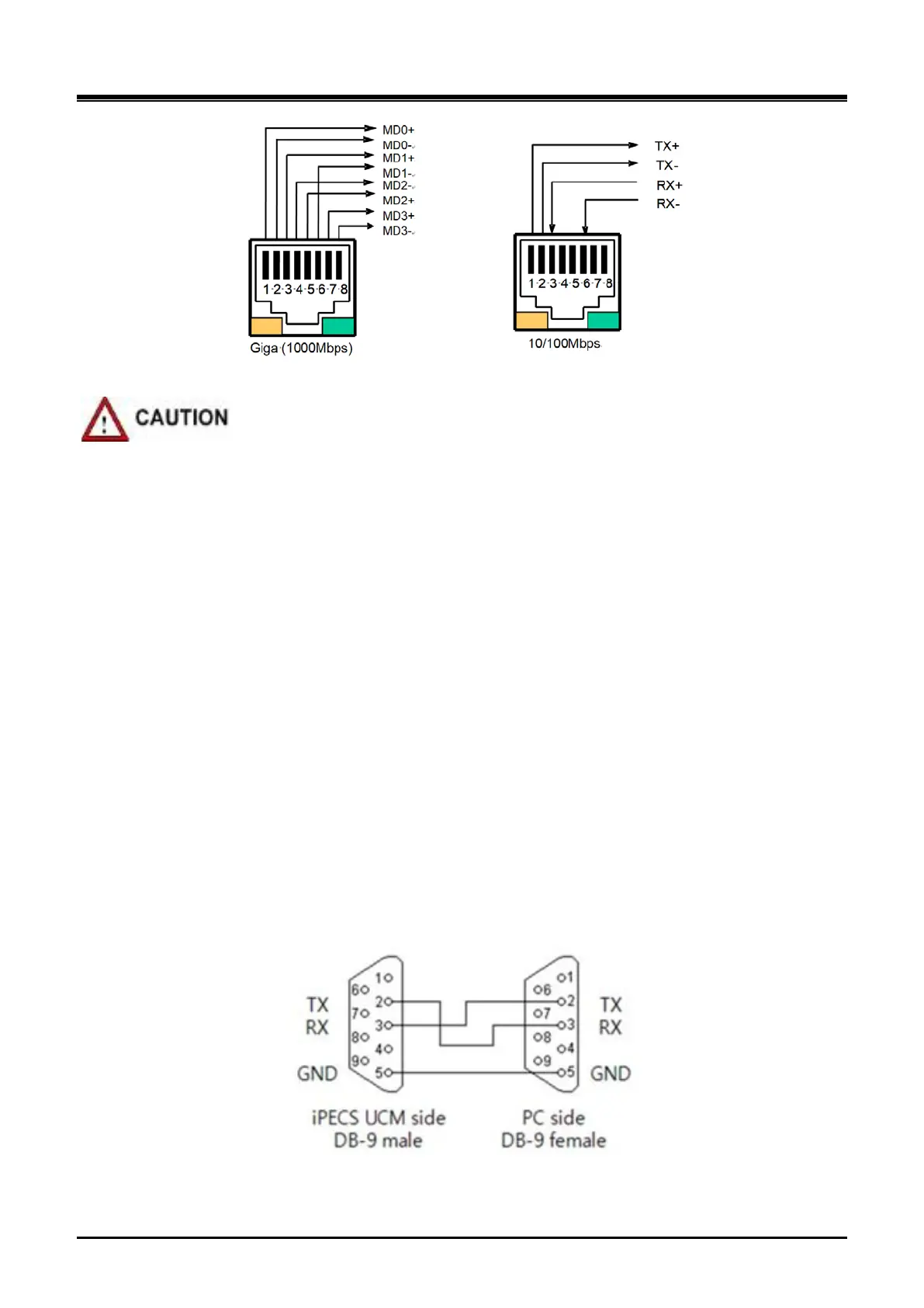
Figure 3-40 LAN Connector (RJ-45) Pin Assignment
If 1000base-T is connected, CAT-5e or CAT-6 UTP cable must be used.
3.6.3 LAN Wiring Structure
The LAN wiring architecture used for connecting the iPECS UCM to the LAN is dependent upon several
factors including:
Shared or iPECS only LAN infrastructure
External VoIP calling requirements
Voice and data network separation or modification in the legacy network
IP phone power option: Adapter or PoE
When the network is shared with other systems, a PC can be connected to the PC port of LIP phone using a
standard LAN cable.
In the shared environment, both data and voice will have access to the WAN, which also permits external VoIP
calling. In the non-shared LAN environments, the system must be connected to the WAN to support external
VoIP connections.
3.6.4 RS-232 Connections
The DB-9 connector located on the rear panel of the cabinet is an RS-232 serial port. The connector is
employed to provide system trace and diagnostic routines for the individual gateway Modules. Two duplicated
ports are provided. For the iPECS UCM RS-232 cable pin assignment, refer to Figure 3-41.
Figure 3-41 RS-232 DB-9 – Pin Assignments