iPECS UCM
Installation Manual Issue 1.1
48
3.4 Call Server Installation
The iPECS UCM provides two types of Call Server, Cabinet type and Module type.
The Cabinet types are UCM-S4K, UCM-S10K and UCM-S30K, It has own cabinet.
The Module type is UCM-S2K which can install in UCM-MGC3 or UCM-1URMC.
3.4.1 UCM-S2K Installation
When the UCM-S2K is mounted in a UCM-MGC3, it can be installed in any of the 11 slots but it is
recommended to install in the left slot, Slot 1 of UCM-MGC3. It can also be installed in UCM-1URMC for
stand-alone operation.
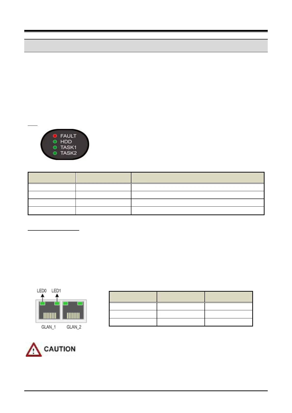
LED
Table 3-8 UCM-S2K Status LED
LED No. Name LED Description
LED 1 FAULT Red LED on when UCM-S2K is abnormal
Green LED blink in the event of SATA SSD disk access
Reserved for S/W
To connect the LAN cable of the UCM-S2K to an external Ethernet switch, connect the cable to the RJ45
connector on the front side of the Gateway Module.
LAN cable connection
If the front cover of UCM-MGC3 is closed, make a through-hole on the front cover to induce the cable outward
as shown in Figure 3-26.
There are two Ethernet port LED on the UCM-S2K and each port has 2 LED (LED0, LED1) for indicating the
Ethernet speed.
LED 0 LED 1 Link Speed
OFF OFF 10 Mbps
ON (Blink) OFF 100 Mbps
OFF ON 1000 Mbps
Figure 3-24 UCM-S2K Ethernet Port LED
Pay attention when using the 1000 base-T (Giga LAN).
The UTP-5e or UTP-6 must be used.