iPECS UCM
Installation Manual Issue 1.1
66
A champ connector to connect E1 / T1 / PRI / SS7 lines is located on the rear side of the UCM-MGC3 / UCM-
1URMC panel in which the UCM-MDTM2 is installed.
Wiring Connectors
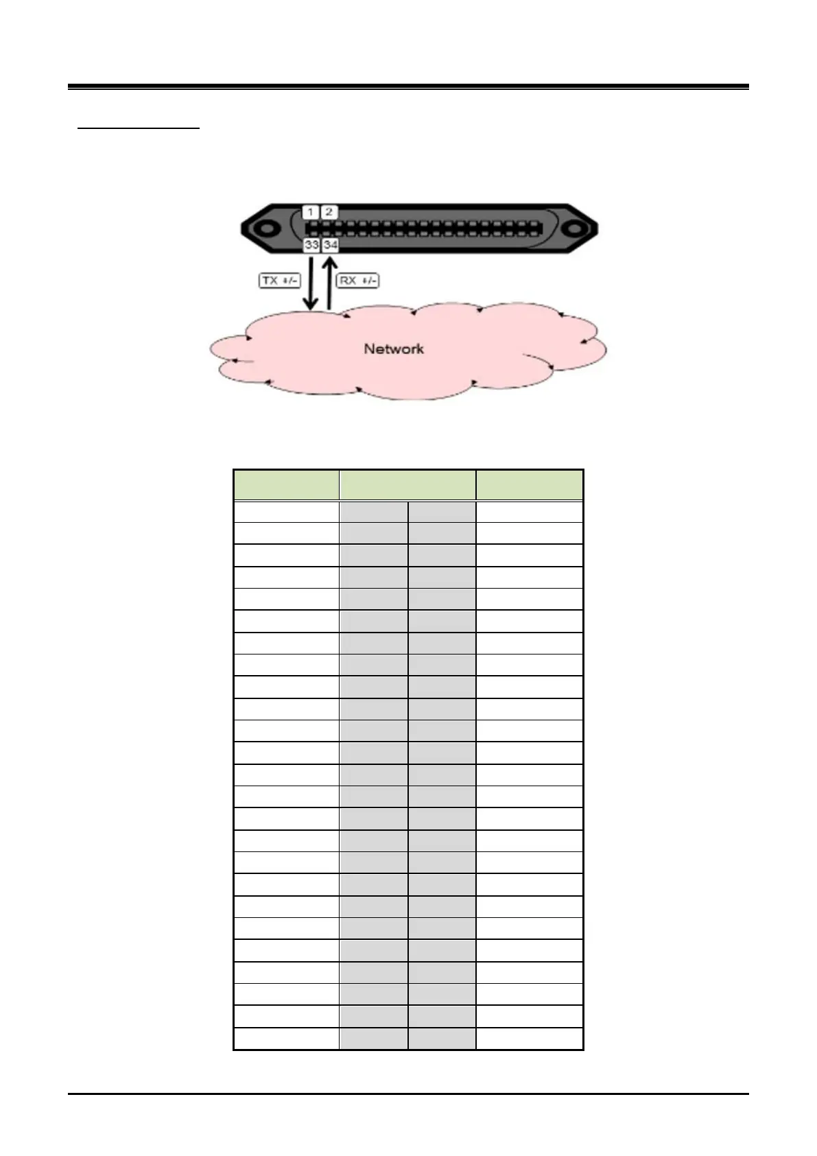
Figure 3-32 UCM-MDTM2 E1/T1/PRI/SS7 LINE Connecting diagram
Champ connector wiring (UCM-MDTM2)
Signal Name Pin No. Signal Name
TX+ 1 33 TX-
R X+ 2 34 RX-
- 3 35 -
- 5 37 -
- 6 38 -
- 8 40 -
- 9 41 -
- 10 42 -
- 11 43 -
- 12 44 -
- 14 46 -
- 15 47 -
- 17 49 -
- 18 50 -
- 19 51 -
- 20 52 -
- 21 53 -
- 23 55 -
- 24 56 -