Do you have a question about the janitza UMG 503 and is the answer not in the manual?
| Device Type | Power Quality Analyzer |
|---|---|
| Measurement Category | CAT III 600V |
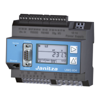
| Mounting | DIN Rail |
| Frequency Range | 45...65Hz |
| Energy Measurement | Yes |
| Data Logging | Yes |
| Display | Graphic LCD |
| Communication Interfaces | Ethernet, RS485 |
| Protocols | Modbus RTU/TCP, Modbus RTU |
| Operating Temperature | -10°C to +55°C |
| Storage Temperature | -25...+70°C |
Symbols for dangerous voltage and protective wire connection.
Procedure for checking delivery contents and ensuring safe use.
Instructions for proper and safe operation by qualified personnel.
Steps for device maintenance, cleaning, battery, and disposal.
Contact information and required details for technical assistance.
Description of the device's purpose and application scope.
Explanation of the device's measurement system and data handling.
Guidelines for connecting the auxiliary voltage supply.
Procedures for connecting voltage and current transformers.
Details on bus structure, termination, and cable specifications.
Connecting the auxiliary voltage to the UMG503.
Connecting current and voltage transformers to the device.
Connecting RS485 or RS232 interfaces for communication.
Troubleshooting common issues like dark display, no current, or low current.
Diagnosing and resolving voltage measurement issues.
Addressing phase shift errors and data loss due to battery.
Resolving issues with real power indication and time settings.
Procedures for addressing cases where the device is not working correctly.
Explanation of the three keys and their functions in different modes.
How to navigate between measured values, SELECT, CONF, and PROG menus.
How the UMG503 displays up to three measured values simultaneously.
List of all measurable and calculable quantities.
Manufacturer's default display settings for voltage and current.
Manufacturer's default display settings for power and energy.
Manufacturer's default display settings for frequency and power factor.
Manufacturer's default display settings for energy consumption by tariff.
Manufacturer's default display settings for harmonics and sum values.
Manufacturer's default display settings for date, time, and serial number.
How to view mean values, including averaging times.
How to access and view minimum/maximum values with their occurrence date and time.
How to view real energy consumption and supply data.
How to view reactive energy data, including starting and running times.
Explanation of EMAX calculation and averaging periods.
How EMAX peak values are saved and overwritten monthly and yearly.
How to reset the measuring period for EMAX and the consequences.
How current is measured when voltage input is missing.
Explanation of harmonics, THD, and partial harmonics.
How to delete real and reactive energy data via keyboard or serial interface.
Procedures for deleting highest and lowest recorded values.
How to clear all minimum and maximum values from memory.
Step-by-step guide to deleting individual min/max voltage values.
How to select which mean values are stored in the ring buffer.
How to assign and change averaging times for mean values.
Setting the duration for the real power EMAX measurement period.
Overview of the UMG 503's memory structure (event, peak/lowest, ring buffer).
How to check and estimate the period of storage for the ring buffer.
Description of compressed and uncompressed data formats in the ring buffer.
How to read data from the ring buffer using Modbus.
Demonstrates reading the most recent data set from the ring buffer.
Procedures for reading all data sets from the ring buffer.
Overview of configurable parameters like transformers, interfaces, and addresses.
Details on configuring clock, software release, contrast, and passwords.
Table detailing primary/secondary ratios for transformers and serial interface settings.
Configuration options for relay outputs, event memory, and auxiliary inputs.
Configuration of tariff schedules, date, time, and DST.
Settings for software release, serial number, LCD contrast, and user password.
How to configure the primary and secondary current transformer ratios.
How to configure the primary and secondary voltage transformer ratios.
Setup for RS485 communication, including protocols and terminal resistance.
Setup for RS232 communication, including protocols and connection diagrams.
How to connect the UMG 503 to an external modem via RS232.
How to set a unique address for devices on a bus system.
How to configure the device to record data to its memory areas.
Configuring limits for internal relay outputs (K1, K2).
Connecting and configuring external relay outputs via WAGO bus coupling.
Example of assigning limits to sum real power.
Example of assigning limits to Real Power EMAX.
Example illustrating relay output behavior based on real power limits.
How to enable and select the three-wire measurement option.
How to configure the device to automatically determine or use a stable net frequency.
Setting the time interval for automatic display rotation.
How to activate the feature to cycle through measured values automatically.
How to choose specific measured values for the rotation feature.
Configuring the internal analogue output for current (0-20mA or 4-20mA).
Connecting and configuring external analogue outputs.
How external analogue outputs are identified in the configuration menu.
Selecting and assigning measured values to specific analogue outputs.
Defining the range for analogue output signals.
Configuring the output range (0-20mA or 4-20mA) for the internal analogue output.
Example of programming the analogue output for sum real power.
Example of programming the analogue output for power factor.
How to assign energy types (real, reactive) to the pulse output.
How to set the energy value per pulse for the output.
Setting the number of events to be saved in the event memory.
Using auxiliary input to reset the real power EMAX measurement.
Controlling tariff changes using the auxiliary input.
Synchronizing the device clock using the auxiliary input.
How to program functions like reset, tariff changeover, and clock sync using digital inputs.
How tariff changes are managed internally via time programs.
Using auxiliary input for external tariff changeover.
Setting up time programs for internal tariff changeovers.
How to set the device's date and time accurately.
Configuring automatic or manual summer/winter time adjustments.
Information about the device's software version and unique serial number.
How to adjust the LCD display contrast for optimal viewing.
Overview of user, master, and clearance passwords.
How to use the clearance password to release optional functions.
Functions related to user passwords, including locking and resetting.
Functions related to the master password for service purposes.
Available protocols for connecting the UMG 503 to field bus systems.
Details on the service protocol and modem connection setup.
How to retrieve data using Modbus RTU protocol, including addresses and formats.
Settings for baud rate, data bits, parity, and stop bits.
Requirements and settings for operating the UMG 503 with PROFIBUS DP.
How to set the PROFIBUS DP protocol and baud rate.
Differences between Profibus DP V0 and V1 for data transmission.
Using a GSD file for transmitting more measured values via PROFIBUS DP.
Example of transmitting measured values in integer format to a PLC.
Example of transmitting measured values in floating point format to a PLC.
Steps to create a GSD file for PROFIBUS configuration.
Instructions on integrating the GSD file into a PLC program.
Diagrams and setup for connecting to a PC via RS485/RS232.
Diagram for connecting the device to a PC via modem.
Diagram for direct PC connection using RS232.
Diagram for connecting to a PLC via RS485.
Diagram for connecting to a WAGO I/O system via RS485.
Listing of all available data tables in the manual.
Explanation of data types like char, word, long, float, and double.
Table listing current, voltage, and power measured values in float format.
Table listing harmonic and EMAX values in float format.
Table listing harmonic distortion and current values in float format.
Table detailing real and reactive energy values in float format across tariffs.
Table mapping measured values to time information and system time.
Table mapping harmonic and EMAX values to time information and changeovers.
Table listing averaging times for various measured values.
Description of the internal control word bytes and their functions.
Table detailing measured values like current, voltage, and power in integer format.
Table detailing mean values in integer format.
Table listing maximum values for various parameters in integer format.
Table listing minimum values for various parameters in integer format.
Table detailing energy values (real, reactive) in integer format.
How measured values are scaled using factors for integer format.
Mapping of bits to functions for inputs (remote control, tariffs).
Mapping of bits to functions for outputs (limit violations, auxiliary input).
Details on how EMAX peak values are stored by tariff and month.
Overview of PSWbasic features like configuration, data readout, and GSD file creation.
System requirements for installing and running the PSWbasic software.
How to perform simple or expanded configurations using the software.
Process of creating and binding GSD files for PROFIBUS communication.
Details on WAGO function clamps for digital and analogue I/O.
Guidelines for connecting the UMG 503 to the WAGO bus coupling.
Diagrams showing RS485 and RS232 connections for bus coupling.
Table detailing the indicating range and measuring accuracy for various quantities.
Specifications for ambient conditions, voltage, inputs, protection, and testing.
Details on measurement rates, outputs, interfaces, weight, and accuracy.
Information on interference resistance, safety standards, and protection classes.
Dimensions and back-side connections for panel mounting.
Details for DIN rail mounting, including wiring diagrams.
A comprehensive connection example illustrating all major terminals and interfaces.
Brief instructions for configuring the current transformer settings.
Brief instructions for configuring the voltage transformer settings.