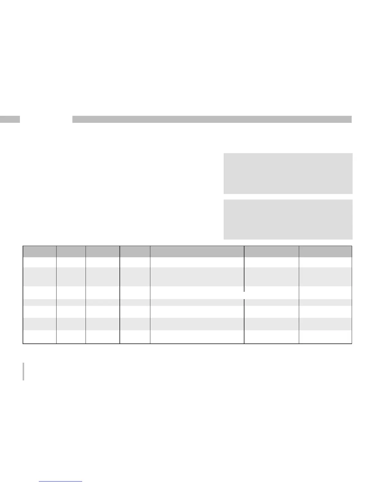
Table 1 – Parameter list
Address format RD/WR Unit Note Adjustment range Default
Parameter and modbus address list
The following excerpt of the parameter list provides
the settings that are necessary for the proper operation
of the UMG 96RM-E, such as current transformer
and device addresses. The values in the parameter list
can be set and read.
The excerpt of the measured value list includes
the measured and calculated values, output status data
and recorded values to be read.
C
A complete overview of the parameters and
measured values as well as explanations
regarding the selected measured values
is filed in the document “Modbus Address
List” on the CD or Internet.
C
The addresses contained in the description
can be adjusted directly on the device
in the range from 0 to 800. The address
range above 1000 can only be processed
via modbus!
(*1)
Values 0 and 248 through 255 are reserved and may not be used.
(*2)
The adjustable value of 0 does not produce any useful work values and must not be used.
0 SHORT RD/WR - Device address 0..255
(*1)
1
1 SHORT RD/WR kbps Baud rate (0=9.6kbps, 1=19.2kbps, 0..7 4
2=38.4kbps, 3= 57.6kbps (5..7 only for
4=115.2kbps) internal use)
2 SHORT RD/WR - Modbus Master 0, 1 0
0=Slave, 1=Master (if Ethernet is provided)
3 SHORT RD/WR - Stoppbits 0..3 0
0 = 1 Bit, none parity
1 = 2 Bits, none parity
2 = 1 Bit, even parity
3 = 1 Bit, uneven parity
10 FLOAT RD/WR A Current transformer I1, primary 0..1000000
(*2)
5
12 FLOAT RD/WR A Current transformer l1, sec. 1..5 5