C
Please note that even before averaging,
the values are divided between positive and
negative ones!
During totalisation, first the totals for the
single phases are calculated, then divided
into positive and negative values!
The maximum values are reset via the “Delete min./max.
values” function with the GridVis program, via Modbus or
on the display by setting the corresponding parameters
(parameter 506: set from 0 to 1).
“Drag indicator”
Max. value of the mean value over n minutes
The “drag indicator” describes a maximum mean value
of a measured value over a defined period.
The period duration is set via a parameter, via the GridVis
software or via the digital input 1.
In the process, synchronisation is triggered via the internal
clock (which can be set via parameter 206 or to a full
hour) or optionally via digital input 1. If synchronisation
via the digital input is selected, the capture time must
be set!
The thee highest values of 15 variables with time stamp
are saved. The maximum values of the variables can also
be viewed in the device display.
Variables:
• Current in the single phases L1.. L3
• Effective power (consumption/export) in the
single phases L1.. L3
• Effective power (consumption/export), total.
• Apparent power the single phases L1...L3
• Apparent power, total
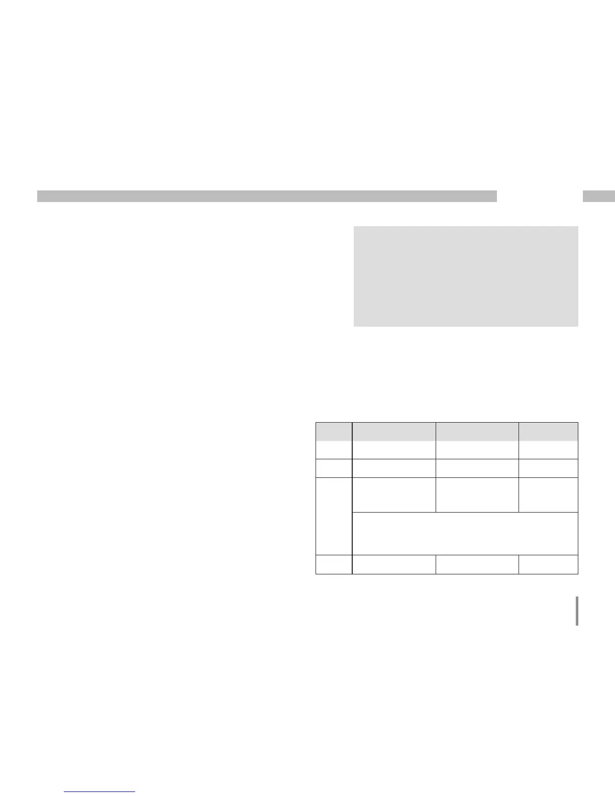
Addr. Description Setting range Presetting
206 Period duration 300 .. 3600 sec. 900
207 Capture time 1 .. 20 sec. 10 sec.
208 Configuration
digital input 1
0 .. 2 0
0 = internal synchronisation
1 = external synchronisation (NO)
2 = external synchronisation (NC)
506 Resetting 0, 1 0