47
X-Series Waterblast Unit
18. Apply Teon tape to the threads of the
lubrication line ttings (Figure 70). Install
the ttings onto the stufng boxes.
19. Apply a light coating of petroleum jelly
or Anti-Seize to the mounting face of the
power end. This will greatly reduce the
buildup of corrosion.
20. Lift the new manifold onto the manifold
mounting studs (Figure 71).
21. Install and adjust the trunnion rod as fol-
lows:
Manifold Trunnion Adjustment
The trunnions in the manifold must be
adjusted such that the hinge rod supports
the manifold to allow the capscrews to be
screwed in or out by hand. The manifold
holes need to be centered over the tapped
holes in the powerframe (or adapter plate).
This conguration will put the hinge rod in
a substantial bind and it will be bent down
slightly at the ends since it will be supporting
the weight of the manifold block. This
centered position of the manifold will also
ensure proper operation of the valves and
seals at all pressures.
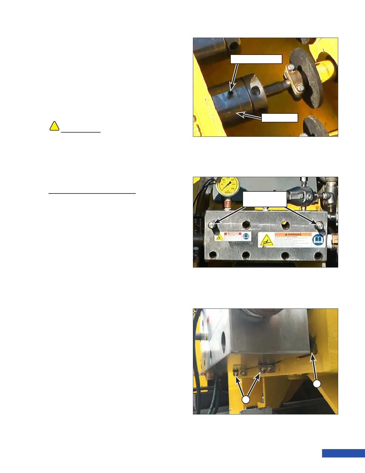
a. Slide the manifold away from the
powerframe (or adapter plate) a few
inches (Figure 72, A). This will allow
room to adjust the threaded trun-
nions in the bottom of the manifold.
b. Screw both manifold trunnions (Fig-
ure 72, B) in completely and then back
them out approximately 2-1/2 turns.
Slide the manifold back against the
powerframe (or adapter plate).
!!
CAUTION
Use two people to lift the manifold. The Manifold
is heavy and failure to use two people may cause
serious injury.
Lubrication Fitting
Stuffing Box
Figure 70: Lubrication Line Fittings.
Figure 71: Lift the New Manifold onto the Mounting Studs.
Manifold Mount-
ing Studs
Figure 72: Manifold in Adjustment Position.
A
B