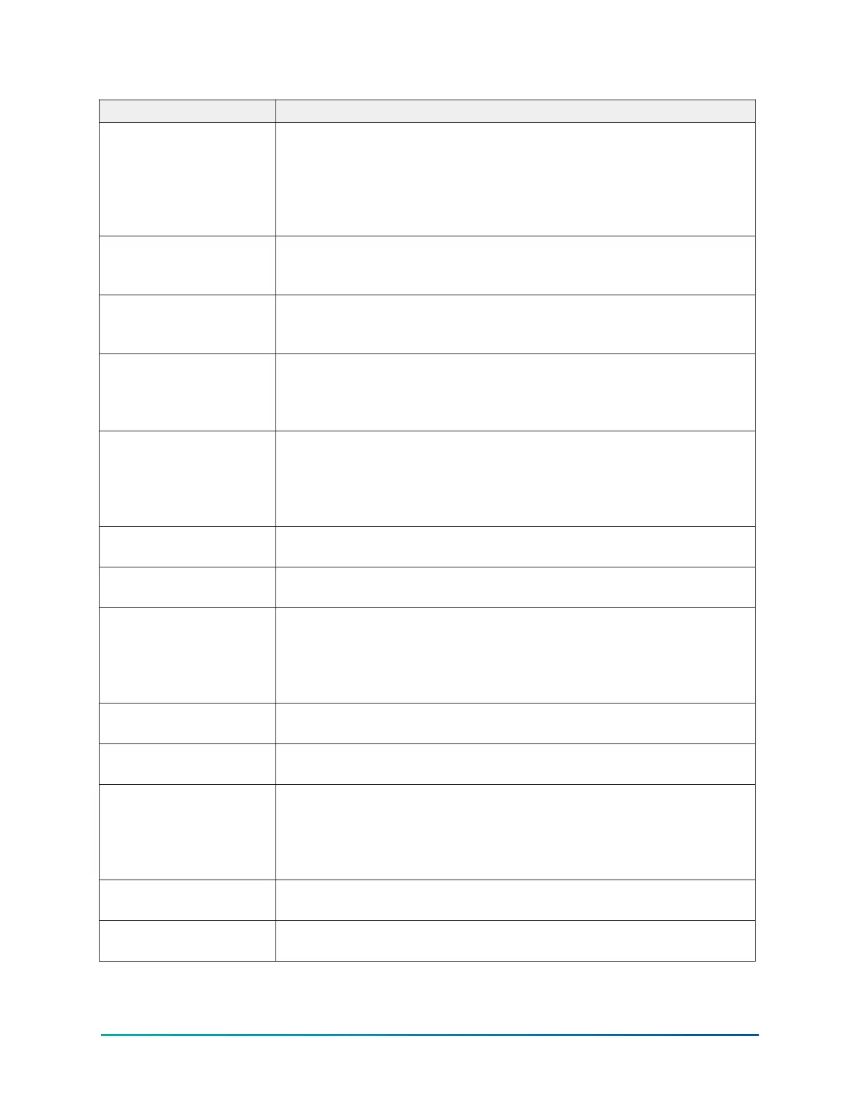
Table 91: Cycling shutdown messages
Message Description
VSD – LOW PHASE
A MOTOR BASEPLATE
TEMPERATURE
The OptiView panel will determine this fault when the temperature of
the motor baseplate phase A has decreased below the low limit of 37°F
(2.7°C). All phase temperatures have to increase above the fault-reset
threshold of 42°F (5.5°C), for this fault to be cleared. The cooling fans
and pumps will turn on while this shutdown is present. They will turn
off when the temperature rises above the fault-reset threshold.
VSD – LOW PHASE
B MOTOR BASEPLATE
TEMPERATURE
See VSD – LOW PHASE A MOTOR BASEPLATE TEMPERATURE message
preceding.
VSD – LOW PHASE
C MOTOR BASEPLATE
TEMPERATURE
See VSD – LOW PHASE A MOTOR BASEPLATE TEMPERATURE message
preceding.
VSD – NOT RUNNING
The OptiView panel will determine this fault when the VSD has not
reported run state via serial communications for 8 seconds while the
microboard issues a VSD run command. The fault is released when the
microboard command is “Stopped State”.
VSD – PHASE A INPUT
DCCT OFFSET
When the VSD begins precharge, the output of the input current Direct
Current Current Transformers (DCCT) are evaluated to ensure that
they are reading zero current when no current is flowing through the
DCCT. If the zero current output value is above a threshold, then this
shutdown is generated.
VSD – PHASE B INPUT
DCCT OFFSET
See VSD – PHASE A INPUT DCCT OFFSET message preceding.
VSD – PHASE C INPUT
DCCT OFFSET
See VSD – PHASE A INPUT DCCT OFFSET message preceding.
VSD – PHASE A INPUT
GATE DRIVER
The gate driver board for the input rectifier monitors the power
supplies within the gate driver circuit, and verifies that the input
rectifier can be properly controlled. If the gate driver monitor
determines that the input rectifier cannot be properly controlled, then
the drive will shutdown and display this message.
VSD – PHASE B INPUT
GATE DRIVER
See VSD – PHASE A INPUT GATE DRIVER message preceding.
VSD – PHASE C INPUT
GATE DRIVER
See VSD – PHASE A INPUT GATE DRIVER message preceding.
VSD – PHASE A MOTOR
GATE DRIVER
The gate driver board for the motor inverter monitors the power
supplies within the gate driver circuit, and verifies that the input
rectifier can be properly controlled. If the gate driver monitor
determines that the input rectifier cannot be properly controlled, then
the drive will shutdown and display this message.
VSD – PHASE B MOTOR
GATE DRIVER
See VSD – PHASE A MOTOR GATE DRIVER message preceding.
VSD – PHASE C MOTOR
GATE DRIVER
See VSD – PHASE A MOTOR GATE DRIVER message preceding.
123
YMC
2
Mod B with OptiView
™
Control Center
 Loading...


