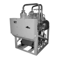
discharges it into the condenser. Cooling water (or other fluid) flowing through the condenser
tubes absorbs heat from the refrigerant vapor, causing it to condense. The cooling water is
supplied to the chiller from an external source, usually a cooling tower. The condensed refrigerant
drains from the condenser into the subcooler section. There it is cooled by the entering condenser
water and exits to into the liquid return line. The level control valve meters the flow of liquid
refrigerant to the evaporator to complete the refrigerant circuit. The level control valve continually
adjusts position as load changes to meet the changed mass flow rate of refrigerant required to
keep the system balanced. It does this by maintaining a constant level in the condenser, enough to
maintain a liquid seal to the outlet.
Capacity control
The major components of a chiller are selected to handle the required refrigerant flow at full load
design conditions. However, most systems will be called upon to deliver full load capacity for only
a relatively small part of the time the unit is in operation. A means exists to modulate capacity for
other loads.
The speed at which the compressor rotates establishes the pressure differential that the chiller can
operate against. This is referred to as ‘lift’. Speed must always be maintained above the minimum
necessary to create the lift required for the pressure difference between the condenser and
evaporator, regardless of load. Below that speed, gas surge occurs. That pressure difference is a
function of the LCHLT and the leaving condenser liquid temperature and the heat transfer between
those liquids and the refrigerant.
Reduced speed also reduces the available capacity of the chiller, when speed reduction is possible.
If speed is reduced, the chiller power use is reduced. Therefore, at reduced capacity requirements
where condenser pressure is also reduced, the motor speed is reduced as much as possible
while maintaining chilled liquid temperature and sufficient lift. When the speed cannot be further
reduced due to lift required for the specified leaving chilled water temperature setting and
available cooling to the condenser and capacity must be further reduced, a mechanism called
Variable Geometry Diffuser (VGD) at the exit of the impeller is used to reduce refrigerant gas flow.
The VGD not only controls capacity, but serves to mitigate “stall”. Stall is an effect caused by slow
refrigerant gas passing through the compressor at reduced flow rates needed for low capacity
operation.
A final optional means to reduce capacity called Hot Gas Bypass (HGBP) is available regardless of
compressor model. When selected for an application, HGBP is used to re-circulate some refrigerant
through the compressor without using it for cooling the chilled liquid. Although this does not
reduce power consumption, it greatly reduces the capacity of the chiller for maximum turndown.
The YMC
2
uses these mechanisms in a controlled order to maintain best efficiency.
The YMC
2
Chiller controls capacity by adjusting the compressor VGD position, the compressor
motor Variable Speed Drive (VSD), and optional Hot Gas Bypass valve (HGBP) position (if equipped)
in a specific sequence depending on whether loading or unloading is required to keep Leaving
Chilled Liquid Temperature at setpoint. Motor speed is additionally and simultaneously adjusted as
necessary to maintain the minimum compressor lift required to prevent surge. The sequence for
operation of the control devices is as follows to achieve the best chiller efficiency:
• Conditions require capacity increase: HGBP (if present) is driven toward closed. Then when
the HGBP is full closed, VGD is driven toward open. Then when the VGD is full open, VSD
speed is increased.
• Conditions require capacity decrease: VSD speed is decreased. Then when VSD speed is at
the minimum limit to avoid surge for the lift, the VGD is driven toward closed. Then when the
VGD reaches closed, the HGBP (if present) is driven toward open.
Also, High Condenser Pressure, Low Evaporator Pressure, High Motor Current, and High Input
Current limits and overrides limit or reduce the output to the appropriate devices (HGBP, VGD, or
VSD) to mitigate the condition to keep the chiller online. As any of these physical thresholds are
YMC
2
Mod B with OptiView
™
Control Center
16

 Loading...


