The Start/Stop control depends whether the chiller Control Source is set to Local or one of the
Remote types from the chiller Setup - Operations screen. Start is operated:
• only the keypad when the chiller is set to local mode,
• remotely through digital inputs in digital or analog remote mode but local keypad start must
be pressed initially to enable the run permissive, or
• by the SC-EQUIP in BAS (ISN) remote mode but local keypad start must be pressed initially to
enable the run permissive.
To start the chiller press the START key on the Home Screen on the display panel. In LOCAL
control source, the chiller then starts. In remote ISN, ANALOG, DIGITAL, or MODEM a remote start
command must also be provided to the correct input connection.
When the control is changed to local mode from any other source, it will remain in RUN if already
running or remain in STOP if already stopped. A hardware Safety Stop button is also located on the
side of the panel.
The chiller will start if the following conditions are met:
• Leaving Chilled Liquid Temperature is above the setpoint
• Chilled liquid flow is established
• Condenser liquid flow is established
• No uncleared faults or start inhibits exist
Chiller operation
Upon start request, the following occur in sequence:
1. Chiller's system pump run contacts close
2. VSD pre-charges (~12 seconds)
3. VSD pre-regulates (~3 seconds)
4. Motor runs
The chiller will vary capacity to maintain the leaving chilled liquid temperature setpoint by a specific
sequencing of optional hot gas bypass, variable geometry diffuser, and compressor speed.
Throughout capacity control, the compressor speed is maintained above the minimum required
for the prevailing head condition, to avoid surge. Otherwise, the device maintaining capacity is
controlled by a proportional-integral-derivative control based on leaving chiller liquid temperature.
Pressure and motor current overrides also apply as necessary to maintain operating limits.
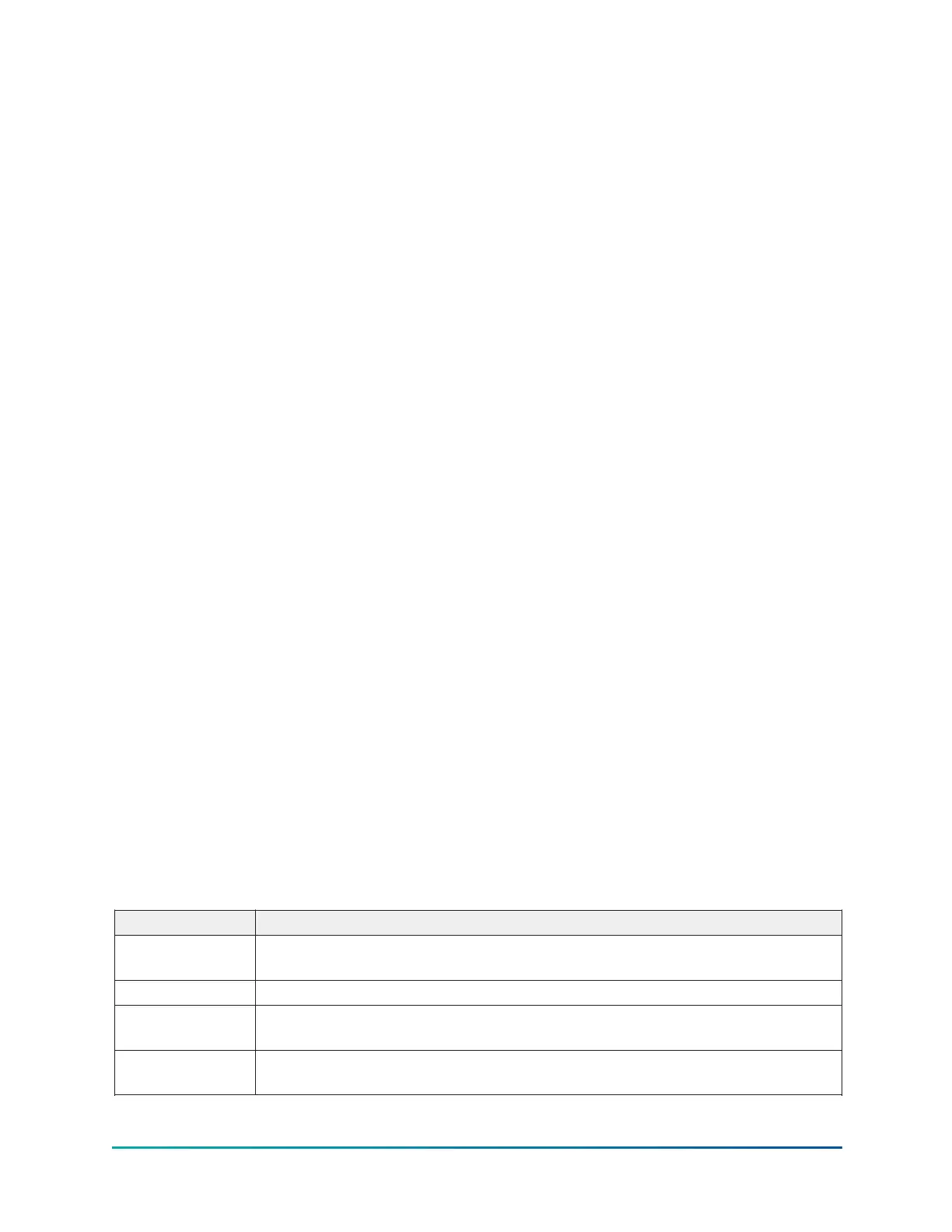
The Input Current limit threshold value is determined from several settings, depending on the
chiller control source selected according to the Table 3.
Table 3: Input current limit threshold
Control source Active input current limit threshold
Local
Lowest of: Local Input Current Limit Setpoint (% Input Job FLA) Pulldown Input
Current Limit (when active)
ISN Remote Input Current Limit Setpoint (comms)
Analog Remote
Lowest of: Local Input Current Limit Setpoint (% Input Job FLA) Analog Remote
Input Current Limit Setpoint Pulldown Input Current Limit (when active)
Digital Remote
Lowest of: Local Input Current Limit Setpoint (% Input Job FLA) Digital Remote
Input Current Limit Setpoint Pulldown Input Current Limit (when active)
YMC
2
Mod B with OptiView
™
Control Center
20