Magnetic bearing controller details screen
Figure 17: Magnetic bearing controller details screen
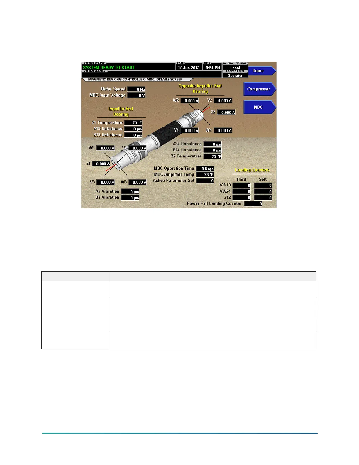
This screen displays the orientation of the magnetic bearing axes relative to the compressor
driveline similar to the MBC Screen. Additional pertinent parameters transmitted to the control
panel from the Magnetic Bearing Controller (MBC) are displayed on this screen. Many parameters
are shown in the diagram in the locations they represent. The left end of the motor shaft graphic
represents the low stage (single stage) Impeller End Bearing. The right end of the motor shaft
graphic represents the Opposite End Bearing.
Table 25: Display only fields
Field/LED name Description
Z1 Temperature
Displays the temperature measured at the impeller end bearing
assembly.
A13 Unbalance / B13
Unbalance
Magnitude of motion at 1x rotation in each of two vectors at the 1-stage
impeller end.
A24 Unbalance / B24
Unbalance
Magnitude of motion at 1x rotation in each of two vectors at the opposite
1-stage impeller end.
Z2 Temperature
Displays the temperature measured at the opposite impeller end bearing
assembly.
51
YMC
2
Mod B with OptiView
™
Control Center