RS-232 PIN ASSIGNMENTS (DB25 PC SIGNAL SET) (OLDER DESKTOPS ONLY)
Pin 1 Protective Ground
Pin 2 Transmit Data
Pin 3 Received Data
Pin 4 Request To Send
Pin 5 Clear To Send
Pin 6 Data Set Ready
Pin 7 Signal Ground
Pin 8
Received line Signal Detector
(Data Carrier Detect)
Pin 20 Data Terminal Ready
Pin 22 Ring Indicator
The connector on the PC has male pins; therefore, the mating cable needs to terminate DB9/
F (female pin) connector.
RS-232 PIN ASSIGNMENTS (DB9 PC SIGNAL SET) (MOST LAPTOPS)
Pin 1
Received line Signal Detector
(Data Carrier Detect)
Pin 2 Received Data
Pin 3 Transmit Data
Pin 4 Data Terminal Ready
Pin 5 Signal Ground
Pin 6 Data Set Ready
Pin 7 Request To Send
Pin 8 Clear To Send
Pin 9 Ring Indicator
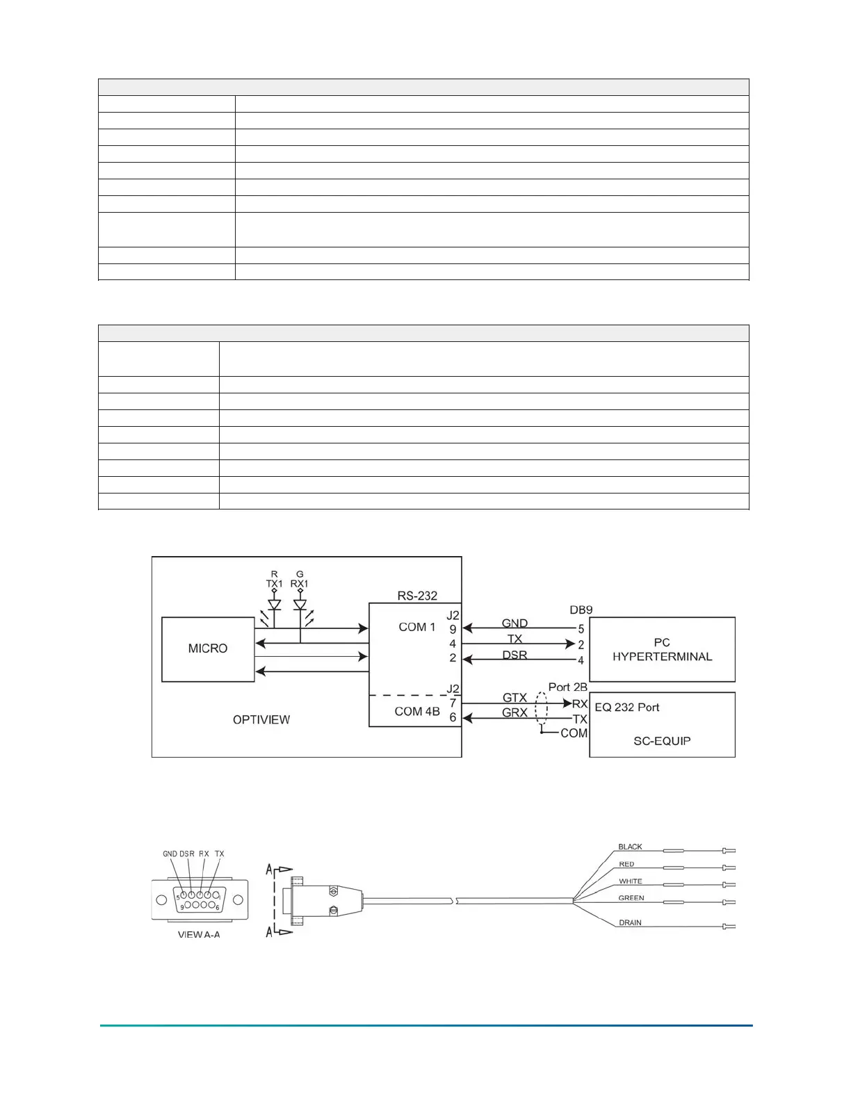
Figure 59: Communications block diagram
A serial cable to go from the OptiView Control Panel to the serial port is available from the
parts center (P/N 075-90490-230).
Figure 60: OptiView panel to PC serial cable
175
YMC
2
Mod B with OptiView
™
Control Center