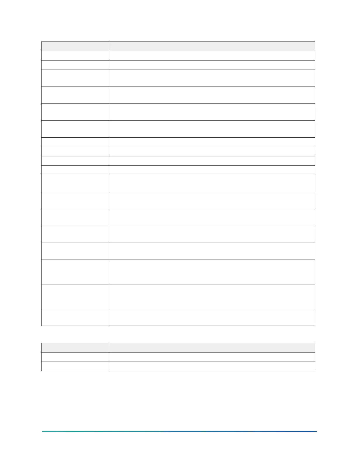
Table 40: Display only fields
Field/LED name Description
Phase Rotation Displays the phase rotation sequencing.
Output Current Rating Indicates VSD size reported from VSD.
Motor Run (LED)
Indicates the digital output from the controls is commanding the motor
to RUN.
DC Bus Regulating
(LED)
Indicates the VSD is regulating the DC Bus.
Precharge Complete
(LED)
Indicates the VSD DC Bus has been pre-charged.
Input Current Limit
(LED)
Indicates the chiller input current is at the Job FLA limit.
Cooling System (LED) Indicates the relay controlling the VSD water pump output is energized.
Precharge Active (LED) Indicates the VSD is pre-charging the DC Bus.
DC Bus Voltage Displays the DC Bus voltage.
Total Supply kVA Displays the total kilovolt-Amps measured by the VSD.
Input Voltage Peak (L1,
L2, L3)
Displays the three-phase input peak voltages measured by the VSD
(Neutral to Line).
Input Voltage RMS (L1,
L2, L3)
Displays the three-phase input RMS voltages across each line.
Input Current RMS (L1,
L2, L3)
Displays the three-phase input current values measured by the VSD.
Output Voltage RMS
(Phase A, B, C)
Displays the three-phase output RMS voltages across each line.
Output Current RMS
(Phase A, B, C)
Displays the three-phase output current values measured by the VSD.
Rectifier Baseplate
Temperature (L1, L2,
L3)
Displays the VSD input rectifier baseplate temperatures at each phase.
Inverter Baseplate
Temperature (Phase A,
B, C)
Displays the VSD output inverter baseplate temperatures at each phase.
Internal Ambient
Temperature
Displays the ambient temperature inside the VSD cabinet from two
sensors as reported by the VSD.
Table 41: Navigation
Button Description
Home Causes an instant return to the Home screen.
VSD Causes an instant return to the VSD screen.
67
YMC
2
Mod B with OptiView
™
Control Center