Chapter 3 INSTALLATION OF THE DISPLAY UNIT
3.6 CONNECTING TO THE GPS COMPASS
3-14
JLR-20/30
Procedure for not using a dedicated cable
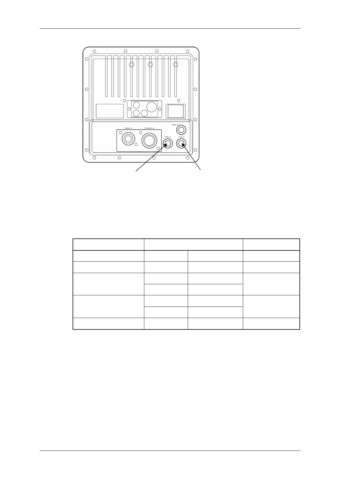
When receiving azimuth information data from the GPS compass, connect the necessary
signal lines to the attached NMEA data connector P5 (for J5) using the following
diagram as the reference.
Signal name GPS compass connector side JMA-3300 side
Compass data input + Disconnected
Disconnected
Compass data input - Disconnected
Disconnected
JLR-10
RADAR-4
Compass data output +
for JLR-20/30
Sensor throw SD-A
③NSKRX+
JLR-10
RADAR-3
Compass data output -
for JLR-20/30
Sensor throw SD-B
④NSKRX-
GND Disconnected
Disconnected
Connect the JRC's GPS receiver
connector.
Connect the CFQ-5469 8-pin connector
labeled with "GYRO COMPASS".
 Loading...


