Chapter 3 INSTALLATION OF THE DISPLAY UNIT
3.6 CONNECTING TO THE GPS COMPASS
3-15
3
NSTALLATION MANUAL
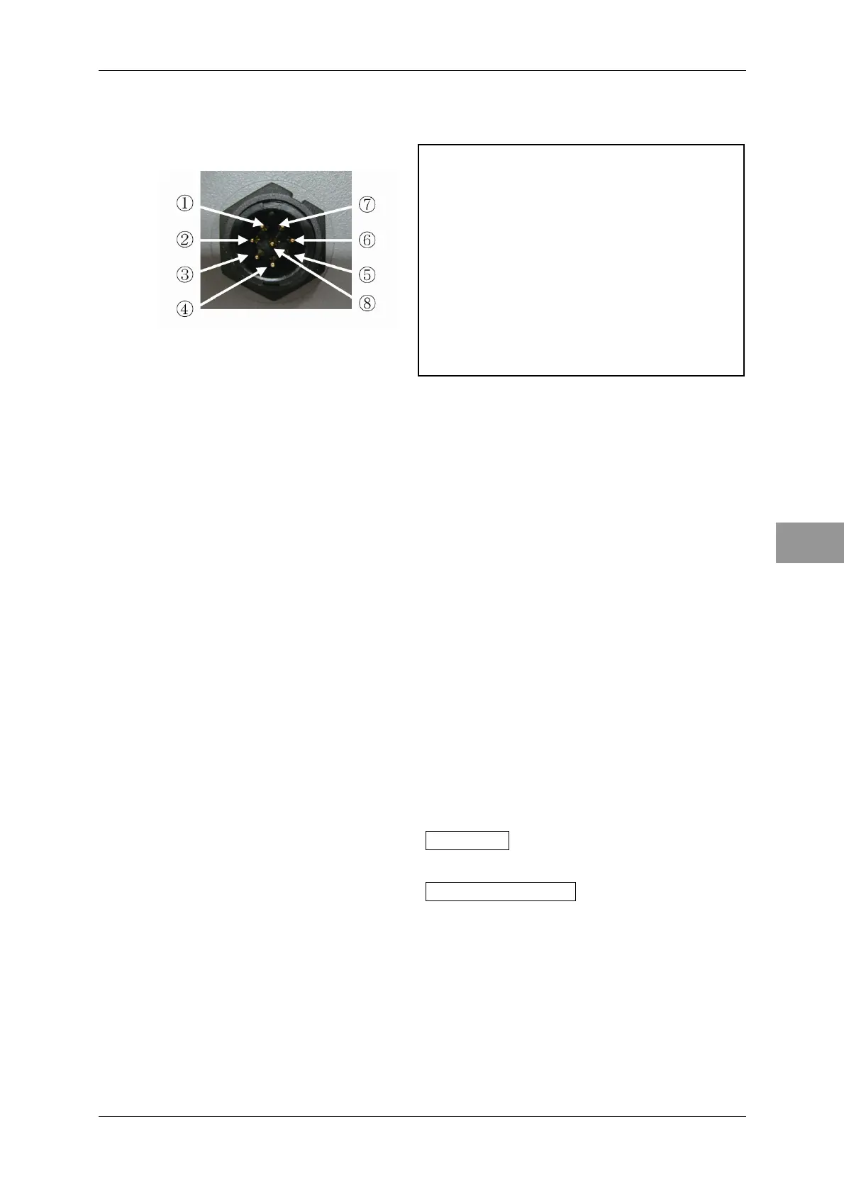
Connector for GPS compass/NSK equipment (J5)
To GPS compass or NSK unit
①NSKTX+ :Sending signals + to HDG
②NSKTX- :Sending signals - to HDG
③NSKRX+ :Receiving signals + from HDG
④NSKRX- :Receiving signals - from HDG
⑤GND :Power GND for NSK
⑥ALM+ :Dry contact output 1
⑦ALM- :Dry contact output 2
⑧+5V :Power for NSK (+5V)
The connections described above are available only for receiving bearing data from
JLR-10/20/30. For details of the position information, refer to "3.5 CONNECTING
TO THE JRC'S GPS RECEIVER".
Setting of the GPS Compass
Set the following information with the GPS compass.
Data output format=NSK
Refer to the instruction manual for the GPS compass for the detailed setting method.
Setting of JMA-3300
Heading Equipment Setting
For details of operations, refer to "4.1 OPENING THE ADJUST MENU" "4.7.2
HEADING EQUIPMENT".
1 Hold down the [MENU] key.
"Code Input" screen appears.
2 Input "0" using the cursor keys, then press the [ENT] key.
"Adjust Menu" screen appears.
3 Press the cursor keys to select I/F Device , then press the [ENT] key.
"I/F Device" screen appears.
4 Press the cursor keys to select Heading Equipment , then press the [ENT]
key.
Selectable items for "Heading Equipment" are displayed.
5 2. Set the gyro.
Baud Rate Setting
When setting the gyro in "● Heading Equipment Setting", the setting of the baud rate is
not required.
 Loading...


