6-9
b. NQE-3141-8A setting
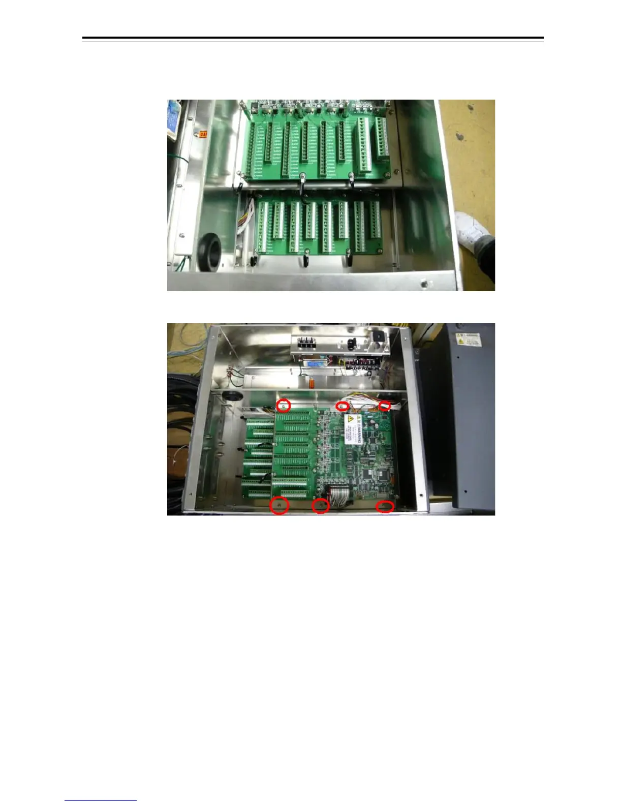
The internal structures of NQE-3141-8A include two unit of CCL-304R in the two-storied structure.
Fig 6-10: NQE-3141-8A Internal structure
Fig 6-11: Access to lower board of NQE-3141-8A
・Although dip switch settings are basically the same as the setting shown in Fig 6-10: Access to
lower board of NQE-3141-8A, it is necessary to make setting for each of the two SW12.
・It is necessary to remove six screws marked in the above drawing in order to access the first story
portion.
・With regand to SW12 board located at the upper position, make setting for CH1 to CH4.
・Whit regand to SW12 board located at the lower position, make setting for CH5 to CH8.
・CH1 to CH4 display on the terminal block mean CH5 to CH8.
・Setting have been made for SW11 and SW13 upen shipment. Do not change those settings.
Factory default setting (bit1 - bit2 - bit3 - bit4)
SW11-upper OFF- OFF- OFF- ON
SW11-lower OFF- OFF- ON- ON
SW13-both OFF- OFF- OFF- OFF
 Loading...


