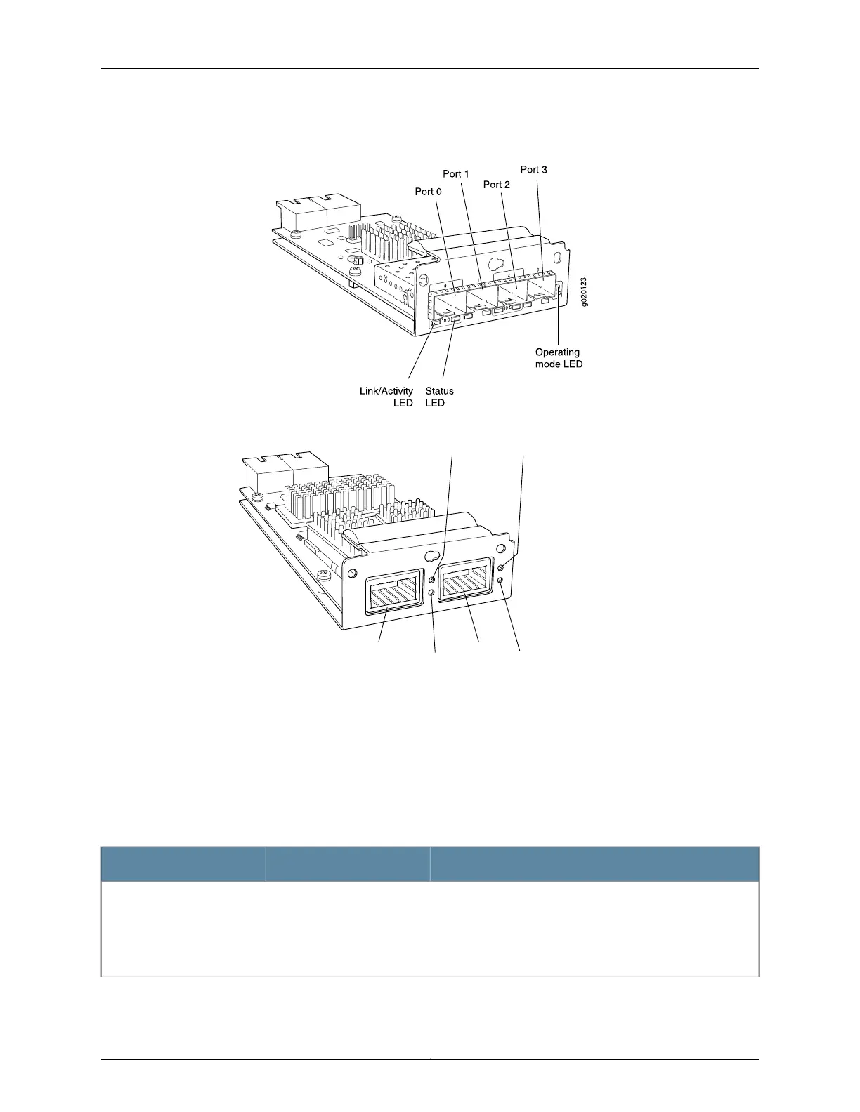
Figure 13: LEDs on the Uplink Module Ports on the SFP+ Uplink Module
Figure 14: LEDs on the Uplink Module Ports on the XFP Uplink Module
g020108
Link/Activity
LED
Link/Activity
LED
Status LED Status LED
Port 0 Port 1
The LEDs labeled Link/Activity LED in Figure 11 on page 21, Figure 12 on page 21, Figure
14 on page 22, and Figure 13 on page 22 indicate link activity. The LEDs labeled Status
LED in Figure 11 on page 21, Figure 12 on page 21, Figure 14 on page 22, and Figure 13 on
page 22 indicate the status of one of the four port parameters. The port parameters are
administrative status, duplex mode, Power over Ethernet (PoE) status, and speed.
Table 7 on page 22 describes the Link/Activity LED.
Table 7: Link/Activity LED on Network Ports in EX3200 and EX4200 Switches
State and DescriptionColorLED
•
Blinking—The port and the link are active, and there is link
activity.
•
On steadily—The port and the link are active, but there is no
link activity.
•
Off—The port is not active.
GreenLink/Activity
Copyright © 2010, Juniper Networks, Inc.22
Complete Hardware Guide for EX3200 and EX4200 Ethernet Switches