Figure 32: EX4200 Switches Mounted on a Single Rack and Connected
in a Ring Topology Using Short and Long Cables: Option 2
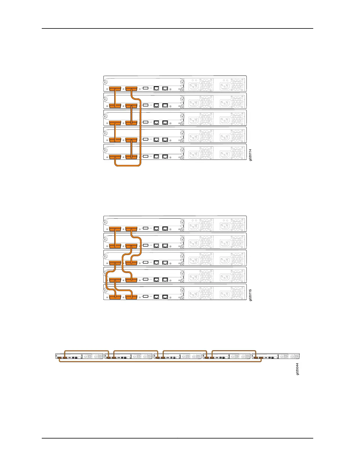
Figure 33 on page 108 shows five EX4200 switches stacked vertically in a rack and
interconnected in a ring topology using short-length and medium-length Virtual Chassis
cables.
Figure 33: EX4200 Switches Mounted on a Single Rack and Connected
in a Ring Topology Using Short and Medium Cables
Figure34 on page 108 and Figure 35 on page 109 show five EX4200 switchesmounted on
the top rows of adjacent racks and interconnected in a ring topology using medium-length
and long-length Virtual Chassis cables.
Figure 34: EX4200 Switches Mounted on Adjacent Racks and Connected
in a Ring Topology Using Medium and Long Cables: Option 1
Copyright © 2010, Juniper Networks, Inc.108
Complete Hardware Guide for EX3200 and EX4200 Ethernet Switches