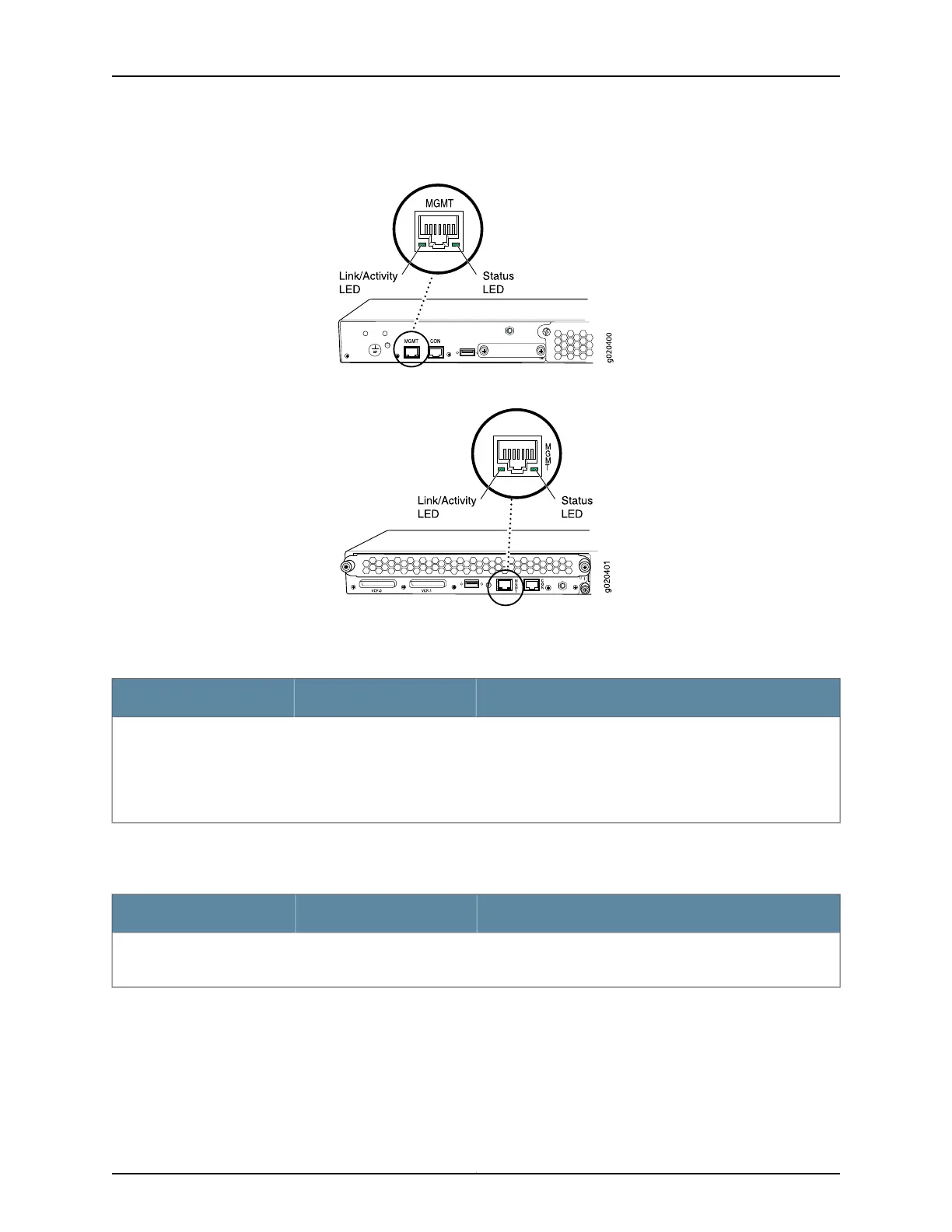
Figure 15: LEDs on the Management Port on an EX3200 Switch
Figure 16: LEDs on the Management Port on an EX4200 Switch
Table 9 on page 26 describes the Link/Activity LED.
Table 9: Link/Activity LED on the Management Port on EX3200 and EX4200 Switches
State and DescriptionColorLED
•
Blinking—The port and the link are active, and there is link
activity.
•
On steadily—The port and the link are active, but there is no
link activity.
•
Off—The port is not active.
GreenLink/Activity
Table 10 on page 26 describes the Status LED (administrative status).
Table 10: Status LED on the Management Port on EX3200 and EX4200 Switches
State and DescriptionColorLED
•
On steadily—Administrative status is enabled.
•
Off—Administrative status is disabled.
GreenStatus
Related Topics See Rear Panel of an EX3200 Switch on page 8 for port location.•
• See Rear Panel of an EX4200 Switch on page 11 for port location.
• Connecting an EX Series Switch toa Network forOut-of-Band Management on page 152
Copyright © 2010, Juniper Networks, Inc.26
Complete Hardware Guide for EX3200 and EX4200 Ethernet Switches