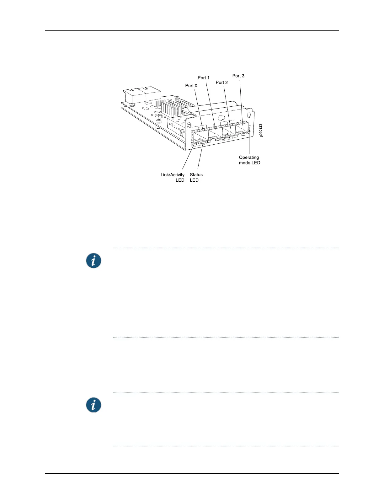
Figure 25: SFP+ Uplink Module
Transceivers are supported in the uplink module’s ports as follows:
•
SFP+ transceivers are supported in ports 0 and 2.
•
SFP transceivers are supported in all four ports.
The ports that support SFP+ transceivers are labeled 10 G on the uplink module’s
faceplate (see Figure 25 on page 36).
NOTE: When an SFP+ uplink module is operating in 10-gigabit mode:
•
Only the 10-gigabit ports (ports 0 and 2) are enabled.
•
You can use only SFP+ transceivers in those ports.
When an SFP+ uplink module is operating in 1-gigabit mode:
•
All four ports are enabled.
•
You can use only SFP transceivers in all four ports.
The SFP+ uplink module has an LED on the faceplate (labeled Operating mode LED in
Figure 25 on page 36) that indicates the operating mode. If the uplink module is operating
in the 10-gigabit mode, the LED is lit. If the uplink module is operating in the 1-gigabit
mode, the LED is unlit.
SFP+ uplink modules are shipped with dust covers preinstalled in the ports.
NOTE: On an EX3200 switch, if you install a transceiver in an SFP+ uplink module when
the uplink moduleis operatingin the 1-gigabit mode, a correspondingnetwork port from
the last four built-in ports is disabled. For example, if you install an SFP+ transceiver in
port 2 on the uplink module (ge-0/1/3), then ge-0/0/23 is disabled. The disabled port
is not listed in the output of show interface commands.
Copyright © 2010, Juniper Networks, Inc.36
Complete Hardware Guide for EX3200 and EX4200 Ethernet Switches