• Removing a Fan Tray from an EX3200 or EX4200 Switch on page 176
Cooling System and Airflow in an EX4200 Switch
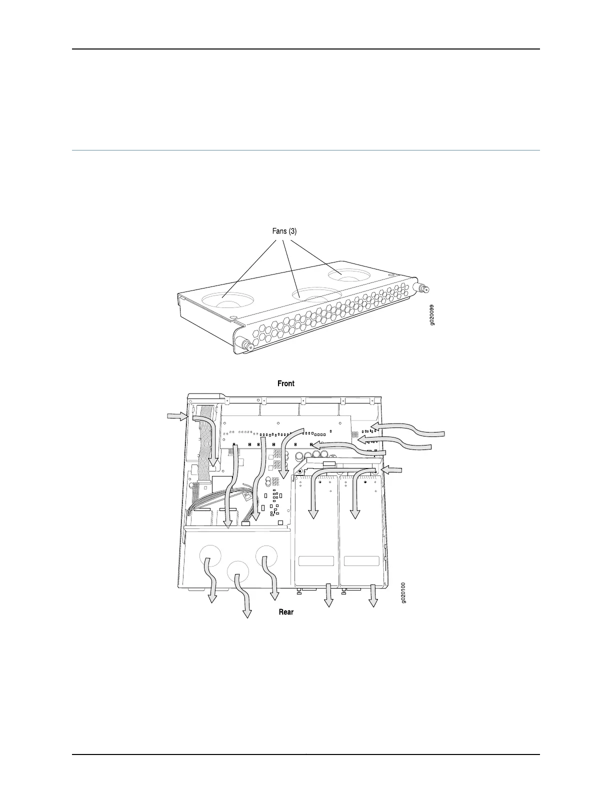
The cooling system in an EX4200 switch consists of a field-replaceable unit (FRU) fan
tray with three fans (see Figure 22 on page 33). The fan tray is located at the rear of the
chassis and provides side-to-rear chassis cooling (see Figure 23 on page 33).
Figure 22: Fan Tray Used in an EX4200 Switch
Figure 23: Airflow Through the EX4200 Switch Chassis
The fan tray used in an EX4200 switch comes with load-sharing redundancy that can
tolerate a single fan failure at room temperature (below 45° C/113° F) to still provide
sufficient cooling.
Temperature sensors in the chassis monitor the temperature within the chassis. The
system raises an alarm if the fan fails or if the temperature inside the chassis rises above
permitted levels. If the temperature inside the chassis rises above the threshold, the
33Copyright © 2010, Juniper Networks, Inc.
Chapter 2: Component Descriptions