Ensure that you have the following parts and tools available:
•
A Phillips (+) screwdriver, number 2
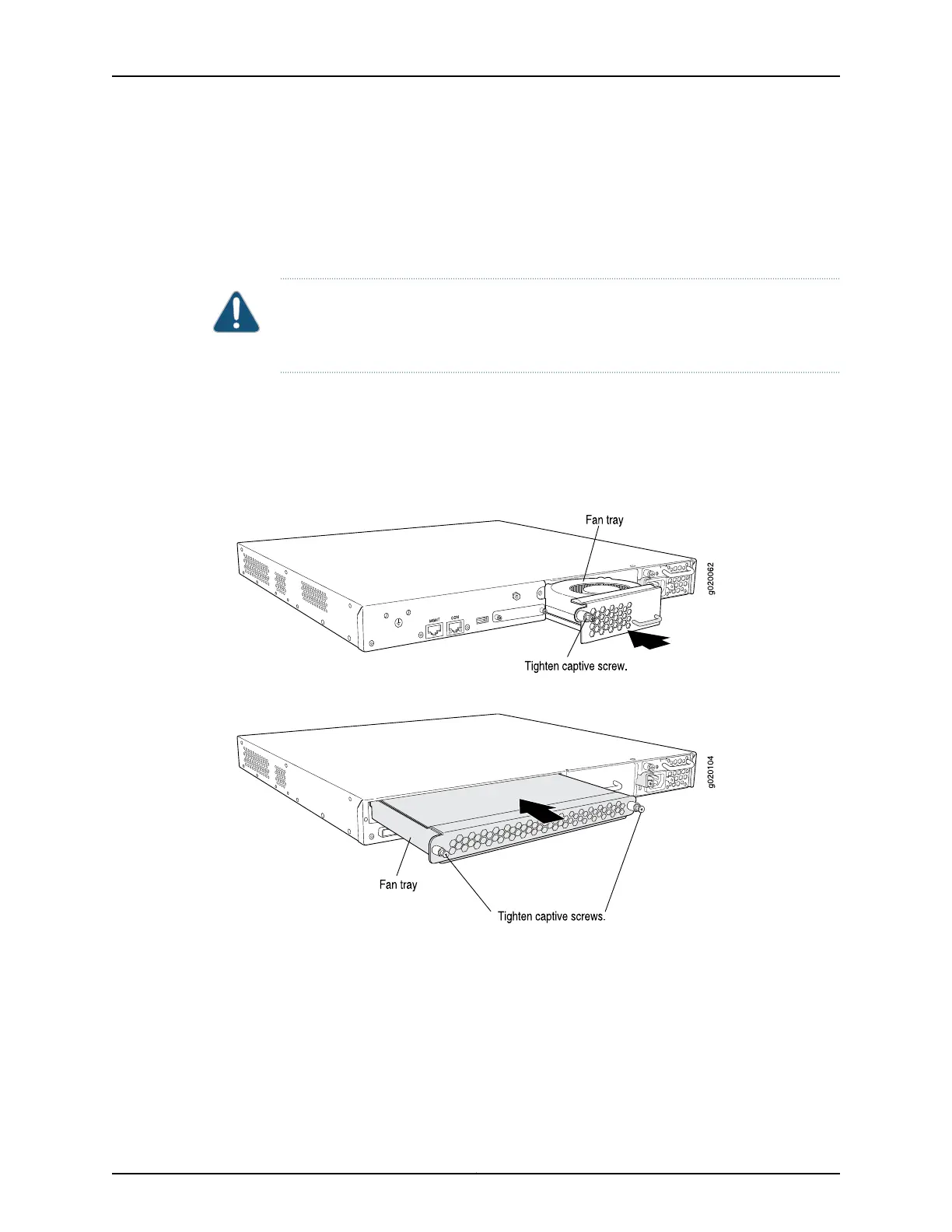
To install a fan tray in an EX3200 or EX4200 switch chassis (see Figure 47 on page 134
and Figure 48 on page 134):
CAUTION: If you are installing a fan tray in an EX3200 switch, ensure the fan faces
upwards. If you are installing a fan tray in an EX4200 switch, ensure the fans face
downwards.
1. Remove the fan tray from its bag. Using both hands, align the tray with the fan tray
guides on the fan tray slot on the rear panel of the chassis and slide it in until it is
fully seated.
2. Tighten the screw or screws on the fan tray by using the screwdriver.
Figure 47: Installing a Fan Tray in an EX3200 Switch
Figure 48: Installing a Fan Tray in an EX4200 Switch
Related Topics Removing a Fan Tray from an EX3200 or EX4200 Switch on page 176•
• Installing and Removing EX3200 and EX4200 Switch Hardware Components on
page 131
• Cooling System and Airflow in an EX3200 Switch on page 31
• Cooling System and Airflow in an EX4200 Switch on page 33
• Field-Replaceable Units in EX3200 and EX4200 Switches on page 18
Copyright © 2010, Juniper Networks, Inc.134
Complete Hardware Guide for EX3200 and EX4200 Ethernet Switches