3. Gently pull the release pull tab on the Virtual Chassis cable connector to release the
lock holding the Virtual Chassis cable connector in the Virtual Chassis port.
4. Gently pull the Virtual Chassis cable connector out of the Virtual Chassis port.
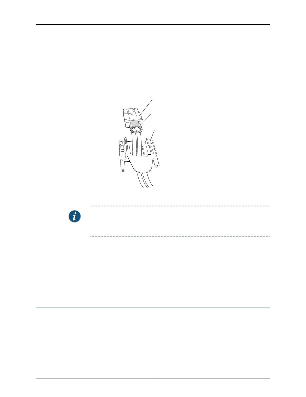
Figure 73: Virtual Chassis Cable Connector in an EX4200 Switch
g020121
Virtual Chassis cable connector
Release pull tab
Cable connector retainer
NOTE: If you order Virtual Chassis cables separately, you must reuse the locking covers
provided with the original cable or order Virtual Chassis cable locking covers also
separately.
Related Topics Connecting a Virtual Chassis Cable to an EX4200 Switch on page 139•
• Understanding Virtual Chassis Hardware Configuration on an EX4200 Switch on
page 105
• Understanding Virtual Chassis Components
• Planning the Virtual Chassis on page 106
• Virtual Chassis Ports Connector Pinout Information for EX4200 Switches on page 81
Replacing a Member Switch of a Virtual Chassis Configuration (CLI Procedure)
You can replace a member switch of a Virtual Chassis configuration without disrupting
network service for the other members. You can retain the existing configuration of the
member switch and apply it to a new member switch, or you can free up the member ID
and make it available for assignment to a new member switch.
183Copyright © 2010, Juniper Networks, Inc.
Chapter 13: Removing Switch Components