• Checking Active Alarms with the J-Web Interface
• Understanding Alarm Types and Severity Levels on EX Series Switches
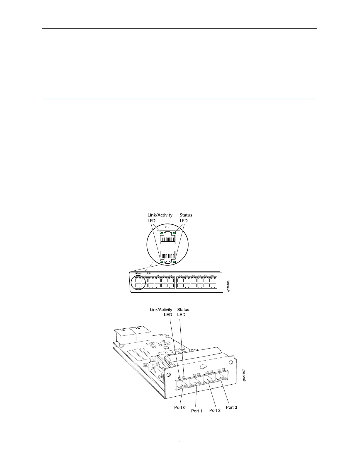
Network Port LEDs in EX3200 and EX4200 Switches
Each network port on an EX3200 or EX4200 switch has two LEDs. The four figures in
this topic show the location of those LEDs:
•
Figure 11 on page 21 shows the location of the LEDs on the network ports on the front
panel.
•
Figure 12 on page 21 shows the location of the LEDs on the uplink module ports on the
SFP uplink module.
•
Figure 13 on page 22 shows the location of the LEDs on the uplink module ports on the
SFP+ uplink module.
•
Figure 14 on page 22 shows the location of the LEDs on the uplink module ports on the
XFP uplink module.
Figure 11: LEDs on the Network Ports on the Front Panel
Figure 12: LEDs on the Uplink Module Ports on the SFP Uplink Module
21Copyright © 2010, Juniper Networks, Inc.
Chapter 2: Component Descriptions