EasyManuals Logo

Juniper EX3200 Series User Manual

Juniper EX3200 Series
280 pages
To Next Page IconTo Next Page
To Previous Page IconTo Previous Page
Page #121 background imageLoading...
Page #121 background image
that the exhaust from other equipment does not blow into the intake vents of the
chassis.
Leave at least 24 in. (61 cm) both in front of and behind the EX3200 or EX4200 switch.
For service personnel to remove and install hardware components, you must leave
adequate space at the front and back of the switch. NEBS GR-63 recommends that
you allow at least 30 in. (76.2 cm) in front of the rack or cabinet and 24 in. (61 cm)
behind the rack or cabinet.
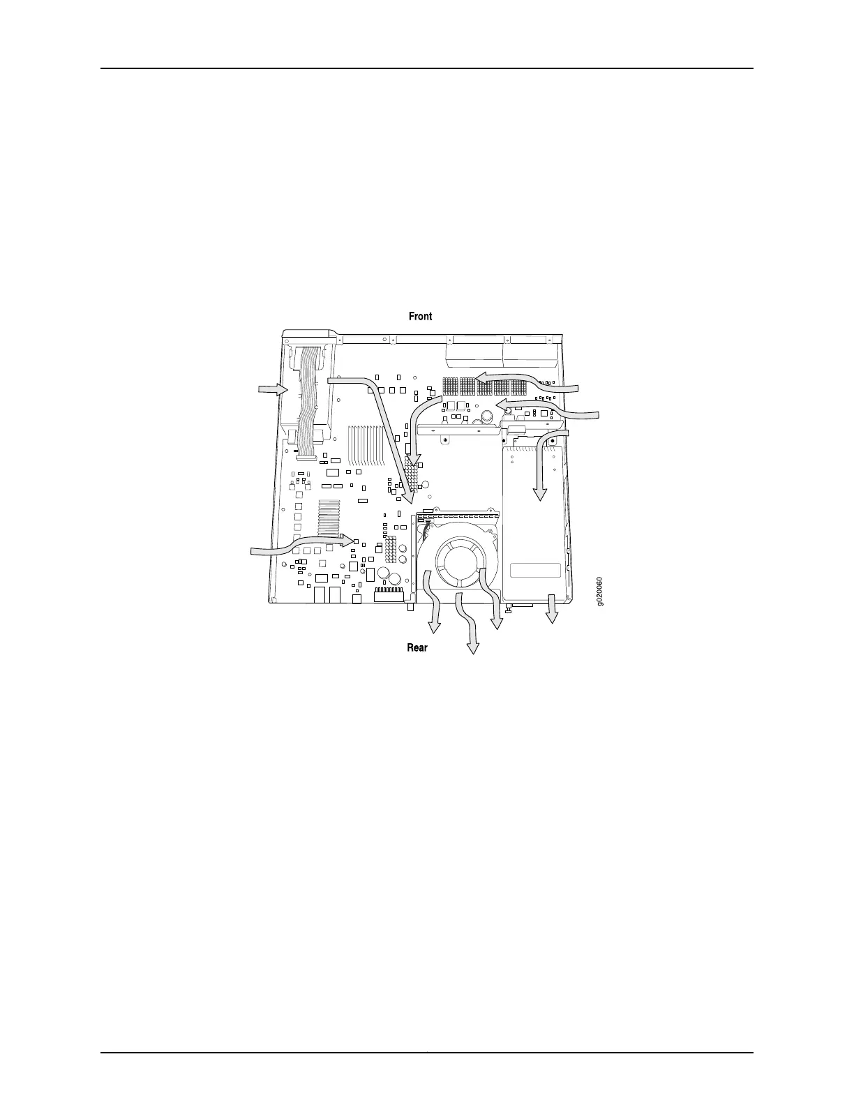
Figure 28: Airflow Through the EX3200 Switch Chassis
97Copyright © 2010, Juniper Networks, Inc.
Chapter 5: Mounting and Clearance Requirements

Table of Contents

Questions and Answers:

Question and Answer IconNeed help?

Do you have a question about the Juniper EX3200 Series and is the answer not in the manual?

Juniper EX3200 Series Specifications

General IconGeneral
ModelEX3200 Series
Rack Units1 U
LayerLayer 2/3
Maximum VLANs4094
Ports24 or 48
Power SupplyAC or DC power supply options
Power Supply Voltage100 to 240 VAC or -48 VDC
Operating Humidity10% to 90% non-condensing
Uplink Ports4 SFP or SFP+
Operating Temperature32°F to 104°F (0°C to 40°C)

Related product manuals