6. Verify the chassis components received against the packing list included with the
switch. An inventory of parts provided with an EX3200 or EX4200 switch is provided
in Table 33 on page 119.
7. Save the shipping carton and packing materials in case you need to move or ship
the switch later.
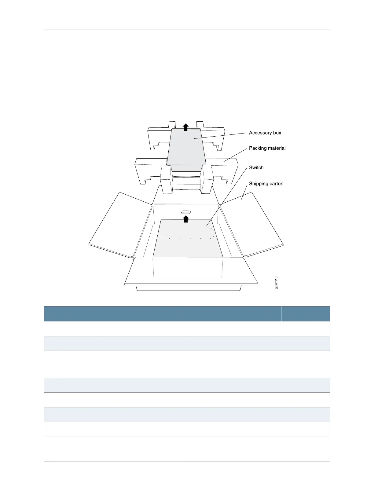
Figure 36: Unpacking an EX3200 or EX4200 Switch
Table 33: Inventory of Components Provided with an EX3200 or EX4200 Switch
QuantityComponent
1Switch
1Fan tray (preinstalled)
1Power supply (preinstalled if your system order includes a 320 W AC power supply; not preinstalled if
your system order includes a 600 W AC power supply, a 930 W AC power supply, or a 190 W DC power
supply)
1Power cord retainer
2Mounting brackets
8Mounting screws
4Rubber feet
119Copyright © 2010, Juniper Networks, Inc.
Chapter 9: Installing the Switch