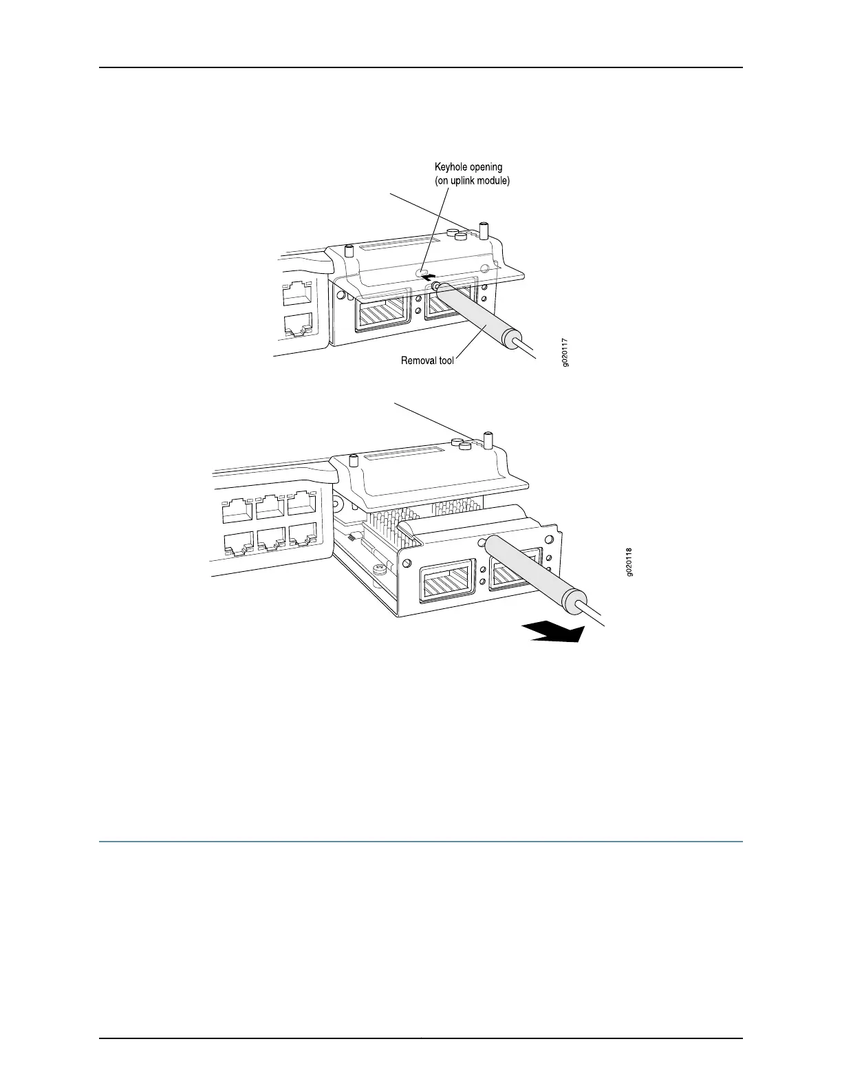
Figure 70: Sliding the Screwdriver to the Narrow Part of the Keyhole
Figure 71: Removing an Uplink Module from an EX3200 or EX4200 Switch
Related Topics Installing an Uplink Module in an EX3200 or EX4200 Switch on page 135•
• Installing and Removing EX3200 and EX4200 Switch Hardware Components on
page 131
• Field-Replaceable Units in EX3200 and EX4200 Switches on page 18
• Front Panel of an EX3200 Switch on page 7
• Front Panel of an EX4200 Switch on page 9
Removing a Transceiver from an EX Series Switch
The transceivers for EX Series switches are hot-removable and hot-insertable
field-replaceable units (FRUs): You can remove and replace them without powering off
the switch or disrupting switch functions.
Before you begin removing a transceiver from an EX Series switch, ensure that you have
taken the necessary precautions for safe handling of lasers (see “Laser and LED Safety
Guidelines and Warnings for EX Series Switches” on page 213).
179Copyright © 2010, Juniper Networks, Inc.
Chapter 13: Removing Switch Components