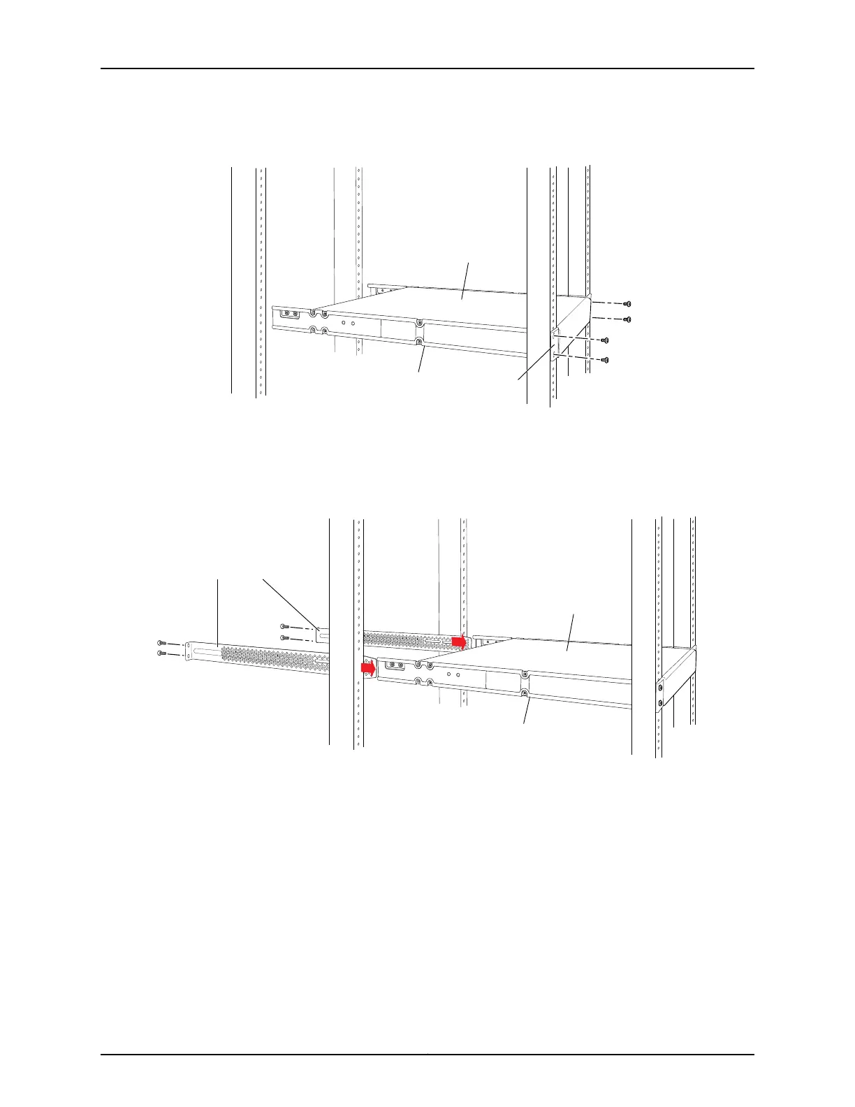
Figure 42: Mounting the Switch to the Front Posts in a Rack
g004477
Side-rail
bracket
Switch
Front
bracket
7. Have a second person secure the front of the switch to the rack by using the
appropriate screws for your rack.
8. Slide the rear brackets into the side-rail brackets. See Figure 43 on page 127.
Figure 43: Sliding the Rear Brackets to the Rear of a Four-Post Rack
g004478
Side-rail
bracket
Switch
Rear brackets
9. Attach the rear brackets to the rear post by using the appropriate screws for your
rack. Tighten the screws.
10. Ensure that the switch chassis is level by verifying that all the screws on the front of
the rack are aligned with the screws at the back of the rack.
11. If the switch is an EX4200-24F model, we recommend that you insert dust covers
in any unused SFP ports.
Related Topics Connecting Earth Ground to an EX Series Switch on page 141•
• Connecting AC Power to an EX3200 or EX4200 Switch on page 147
• Connecting DC Power to an EX3200 or EX4200 Switch on page 149
127Copyright © 2010, Juniper Networks, Inc.
Chapter 9: Installing the Switch